Velomobile development drawings: Part 7

I thought it best to build a prototype to test the steering geometry, as wobbles have been reported. This to be built with aluminium section and composite rear triangle.


This is the geometry involved. The idea of the tilt axle is from Vi Vuong, aka Futon Express, from the USA.

The rear axle uses a bottom bracket system, 100 mm cranks, 15 mm axles and the chain wheel represents a disc brake to stop the tilting.

Chassis with drive structure, longerons, windscreen frame and ‘’gills’’ for bending.

These are the intersections to define body parts and joints.

The final iteration with 26 inch wheels all round.

Velomobile development drawings: Part 6

I looked first at the volume of the space taken up by rotating the feet on 175 mm cranks, and compared that to 140 mm cranks. Being so far forward it makes a difference in the volume of the nose and it is easier to push through air.

Also with this I wanted the following:-

  • A single simple form with no jointed surfaces, spats and head-farings. All joints on exterior surfaces of aircraft have fillets between them to reduce vortex drag.
  • The simplest drive line.
  • A faired recumbent bicycle that did not fall over when you try to get in or stop.
  • I wanted it to tilt into a curve to reduce the loads and stress on the wheel system and chassis so they can be lightly built.

!75 mm compared to 140 mm crank frontal areas

140 mm crank rotational volume.

The chassis bounded volume with 26 inch front wheel and 20 inch rear wheels. The chassis will be built from 3.4 mm Corex and 11.5 mm honeycomb board hot-glue gunned with 12 mm conduit.

Velomobile development drawings: Part 5

I have decided to update this site and describe the line of thought that led to the final design choices, for a velomobile trike.

Getting good airflow over breaks in the surface at the front, is near impossible, so I moved the steering to the rear wheel.

The next stage (body 10) was to try and simplify the form and integrate all the elements using negative pressure and try and do away with surface joints, at the front, as much a s possible.

The wheel spats are more integrated into the nose and the head faring smoothed into the body. I was happy, I had conquered all my demons.

After a short break I returned to this design and gave it a hard critical review. I had lost sight of the friction in the drive line. With so little power available you cannot waste any on extra bearings and changes of direction and weight

Even this simplified form had too many parts and too much wetted surface area.The cross sectional surface area of a reclined human body looking over the knees remains the same. But what about the area of the feet so far forward in a form, what is it, ??? and can it be reduced, ???

Velomobile development drawings: Part 4

In Part 1 of this write up I said the steering geometry is based on the invention of Jurgen Mages and his Python recumbents:-

http://en.openbike.org/wiki/Main_Page

There has been a great deal of discussion and argument about the best steering angles for any size wheel in any application of the bicycle, road racing, track, mountain bike, shopping bike. All have their subtle variations in angles and trail, all to do with where the tyre meets the ground and pivots. Then along comes Jurgen who places the steering head behind the wheel, does not attempt any of the known rules and it works.

What Jurgen discovered was that at a steering head angle of +/- 65 degrees as the steered wheel is turned the frame rises. The weight of the rider pushes back down stabilising the system.

I refer to Python Projects Survey  http://www.python-lowracer.de/projects.html   where I find the trail figure for a 20 inch wheel is +/- 140 mm and a steering pivot angle of 57.5 – 71 degrees. Now I know this is for two wheeled vehicles and I am designing a three wheeled vehicle but you have to start somewhere.

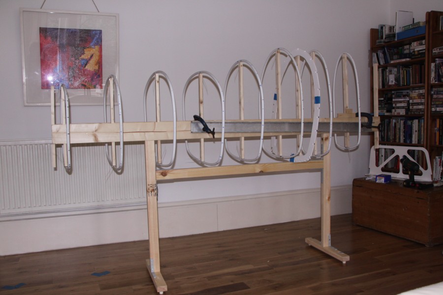
At this point in this project I have developed a simple idea. I have looked at wheel sizes, axles, airflow, body shape by profile stacking, rotation, and extrusion. I have enough toys to play with.

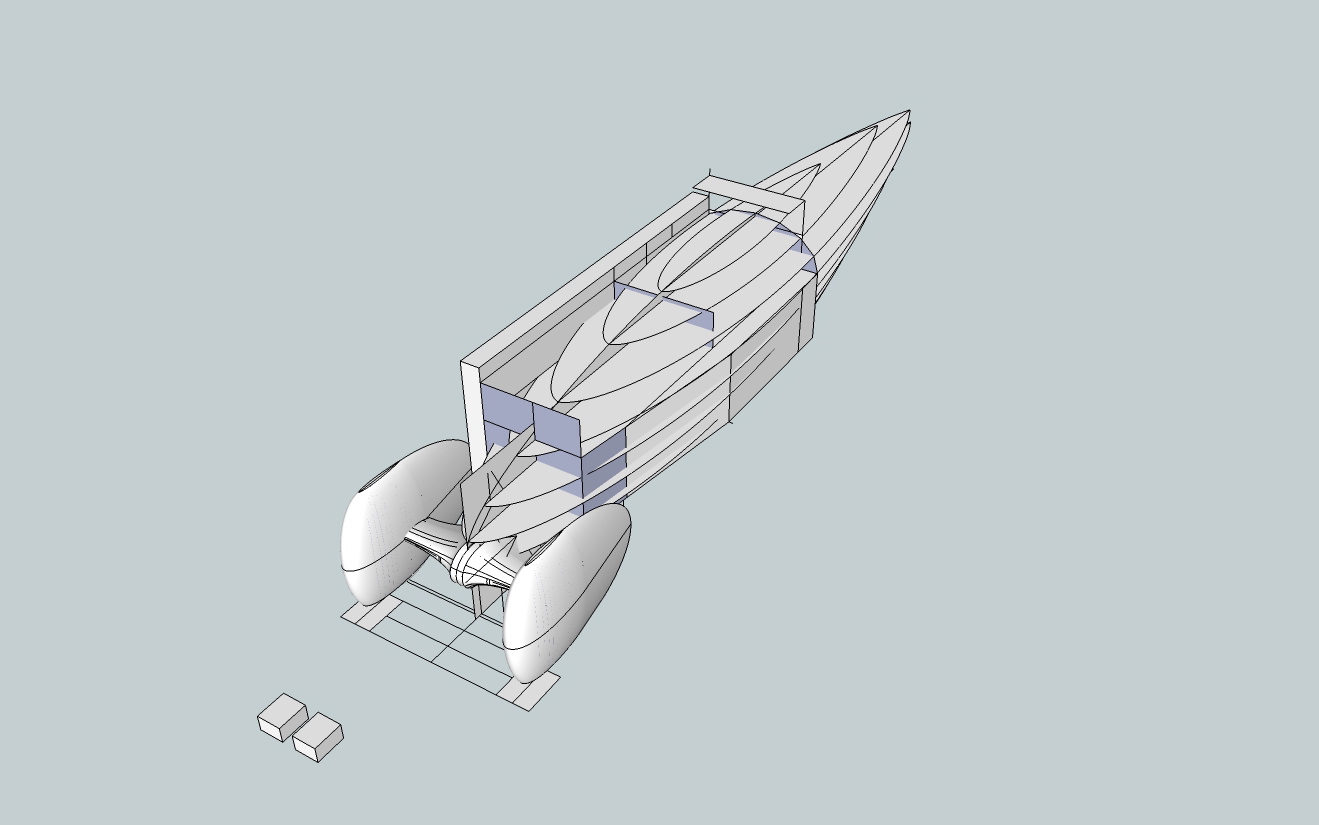
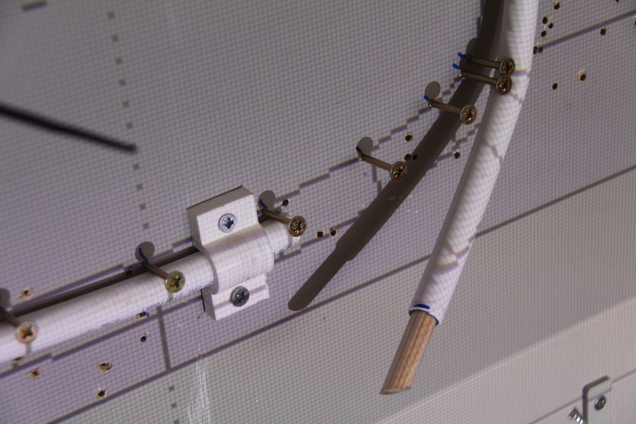
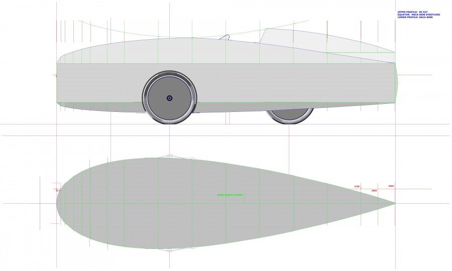
Now is the time to measure the movement in the body structure to give a reasonable turning radius. To do this I use the original Chassis Bounded Volume set up with 20 inch wheels. The file is smaller and takes less generating time. It also allows me to check I am not entering any clearance borders.
Importantly it will also show where a chassis will have to reach to tie it all in to a structure. I take the axle and wheels and add a rotation block with its axis at the point where the 65 degree steering angle meets the ground.

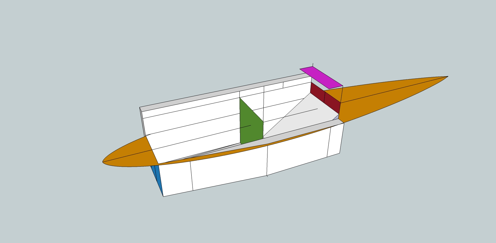
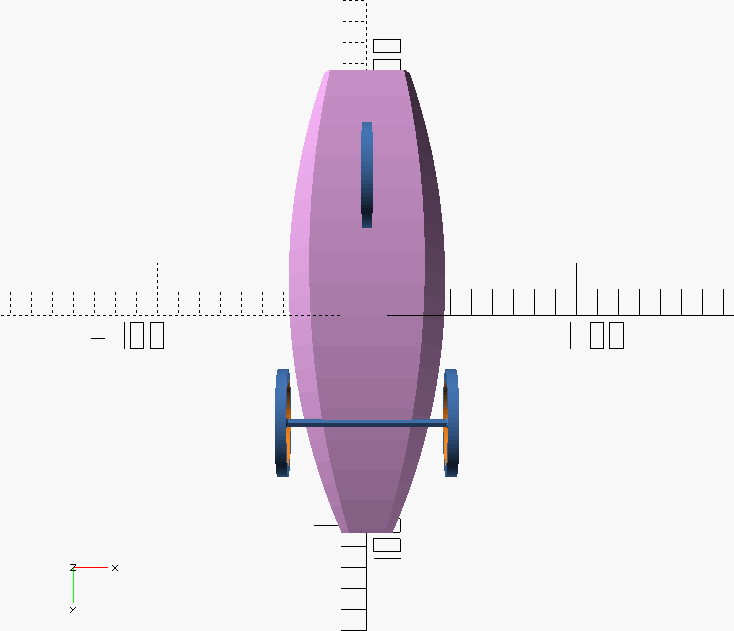
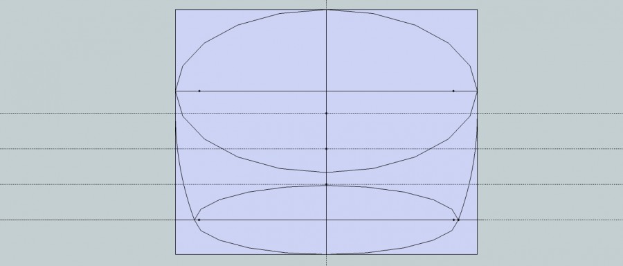
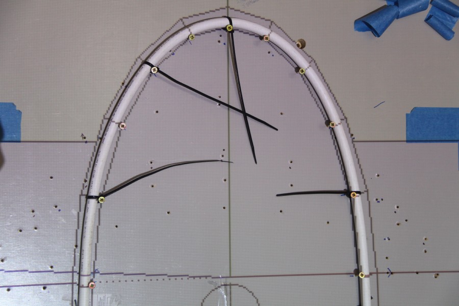
I then place a circle at the origin (the centre of the 3 axiis) and make it a Component. The axle, which is a separate Component is then placed with the trail point at the origin, and tilted forward. Both components are then made a Group. When the Group is tilted back so the axle is level the handling circle is now at 25 or 65 degrees. When the rotation tool is applied the handling circle the axle rotates at 65 degrees to the horizontal. I then position the axle to the correct point on the body and rotate the axle. Axle and body are now combined as a Group. When the Group is rotated to get the axle level the body leans away from the turning direction.

At this point, I reversed the direction of the steering pivot, everything else remains exactly the same. The body now leans into the turning direction. By the findings of Jurgen the geometry is self centering so to pull the body back upright release the steering.


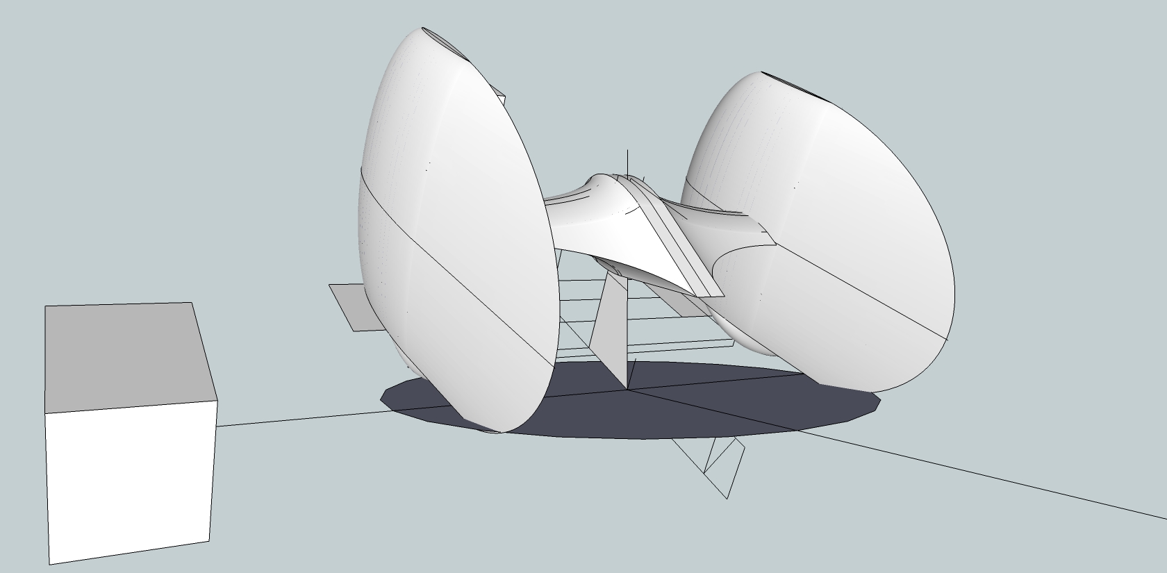
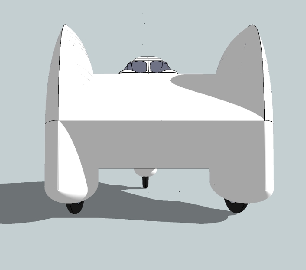
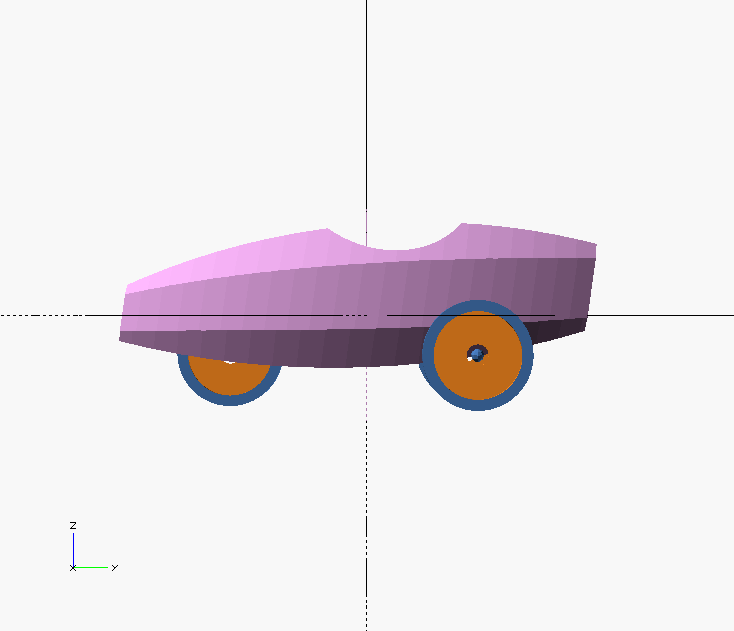
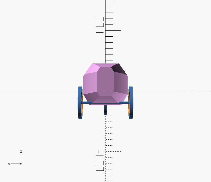
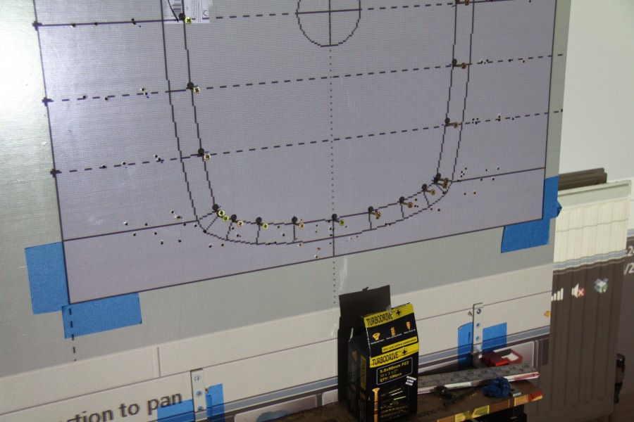
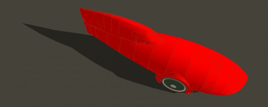
I repeated the process with the rendered body and the 26 inch wheels and straight axle to check for clearance, and this is what you get. I still have to carry on with the development of the one piece axle/nose and body bending design, but this is a good indication the geometry might work.

When I started out to design something I did not ‘see’ before, I did not expect this, but that is why you do it.

Velomobile development drawings: Part 3

In various drawings you will see blocks and cubes dotted around. These are for handling, they allow you to manipulate the component accurately, Sketchup rotation tools have a hard time handling curved surfaces.

Now I have a quick-and-dirty knock up drawing. some parts are accurately placed but nothing is fixed or final.

The only restriction I have placed on this design is that the maximum width is 800 mm, to go through a door in my apartment.

The first thing I checked for was the sight line, it was way too long.
So I redesigned the body with a straight line nose profile from just below the eyes and clearing the front axle.
It was so ungainly I am not allowing it out in public. Maybe the theory is sound but it does not always produce pleasing results as I found.
Maybe there is work to be done improving visibility without scaring people.

So I went back to body 1.
I had a 20 inch BMX wheel lying around while i was drawing. The smaller diameter rims have a hard time with the condition of the road and cycle track around here. I drew 26 inch 559 wheels and spats.
The increase in surface wetted area and cross sectional area is offset by the decrease in rolling resistance and tyre availability.

The down side of the larger wheels means the air flow between the spats and nose is becoming more restricted and looks like it will generate higher air pressure and therefore drag.
I act on niggles. I am not very smart and it takes time for things to sink in. Then they start to niggle at me, then I have to do something about it. The problem was always there, it is just exaggerated with larger spats.

The thing I tried was to increase the size of the axle fairing and placed so the air travels up the profile increasing in pressure. However when it goes over the hump on both fairing and spats the pressure will be negative by the time it hits the nose which has effectively pushed back.

Body 3.1 is the same but with an enclosed head fairing and a larger rear wheel spat, but this will cause grounding problems.

Body 3.2 Is another variation on the head fairing.

Body 4 gH2Ost Rerun:  is the beginning of thinking about the engineering of bending the body to steer the wheels.
I have lying about some 100 mm diameter Tumble Dryer hose, 25 mm compressed length stretches out to 120 mm, while retaining it’s circular form. I also have 80 mm hose.
I needed a semi circular cross section round about the trailing edge of the spats. At the same time I took the opportunity to split the body into two zones.
The upper section for the width of the arms and shoulders and the lower for the rib cage, hips and feet. I used E 817 for the upper profile, angling it in from the spats through clearance at the shoulders to the tail.
I went back to Loft Along Path and this time got it to work. This essentially the same system as ‘gH2Ost’ a tapered central flat section with circular rotated profiles on the edge. The air flow underneath needs more work. The air flow on top is improved and the overall shape is simplified.

With my new found success with LAP I went back to body 1 and rendered all the E 214 profiles.

Body 5. With the body 1 chunk I reversed the trike setup and put the spats at the back. This has the chance of excellent airflow well down the form. I can also reduce the overall width down to +/-600 mm.

Velomobile development drawings: Part 2

The next step was to measure the dimensions of the body I am aiming to transport.
I set up a board as seat back and surrounded myself with boxes for the rib cage/hips, shoulders, back of the head, eye line, leg bent and straight for knee height.
The bent knee height sets the velomobile body height which sets the eye line.

I then drew these up as Chassis Bounded Volume. It is NOT a chassis it is only the volumes and boundaries of a human body cycling lying down.
The light blue plane is the flat foot length.
The top edge of the green plane is the knee height and relative distance.
The dark red plane is the back of the shoulders and head The purple plane is the eye line height and distance of the eyes from the back of the head.
The yellow plane is Eppler 214 scaled to clearance fit at the shoulders at the dark red plane.

I then place a station at the red plane with 16 points where 8 X Eppler 214 profiles would pass for minimum clearance.
There is clearance below the Chassis Bounded Volume for sag in the hammock and the 150 mm (6 inch) ground clearance.
A 26 inch 559 rear wheel and the 20 inch 406 wheels, spats and inboard axle, were placed approximately in the right area.

An Eppler 817 hydrofoil profile was chosen because it is designed to work at low flow speeds and is rear loaded, that is its maximum height is well back on the chord line. This was scaled in the vertical plane, only to give a taut profile line to the nose of the body.

As with the front wheel spats the E214 were then laid on the profile line and then scaled to pass through the station. Whatever shape was generated would be exactly right, but I had no idea what it would look like! I thought the nose profile was irrelevant because the E214’s are stacked with no distortions between levels, aah, well, maybe.


Velomobile development drawings: Part 1

My aim in designing this new velomobile was to make it as simple as possible while reducing the effort to push it through the air. I also wanted to make something with as few compromises as possible.

The major influences at work in this design is the invention of Jurgen Mages and his Python recumbent bicycle geometry. This went completely against the RULES of bicycle steering geometry and created bikes which not only steer and handle but have done so over thousands of miles of commuting and touring. Please see in

http://en.openbike.org/wiki/Main_Page

One of the biggest sources of drag in a land traveling vehicles are the holes needed to clear the wheel(s) when they steer. Reduce the clearances to a minimum and you are doing as much as you can.

This image shows the plan view of a 20 inch 406 BMX front wheel. The aero profile is Eppler 214 Low Reynolds number which is calculated for low speed air flow. The ellipse is to give enough clearance for tyre punctures while not creating interference drag. The leading edge profile comes from the ellipse.
I could not imagine what this might look like, so I had to generate it to find out. This latest design completely changed my approach. Usually I draw what I want and then work on it until I am happy with the result. This time I set out the rules and see what comes about and worry about making it later.

The wheel does not pivot in the fairing, so pivot the fairing, this creates aero problems with the axle/fairing join. Simplify the whole front end and make the wheels, fairings and axle one piece. This does away with pivots, uprights, steering arms, rose joints and a mass of nuts bolts and washers.

“Nothing weighs less than nothing”

The next step was to put the disk brakes in-board. The axle then only had to deal with bending forces, all torsional braking forces are dealt with in the central structure leading directly into the chassis.

Make the nose of the body one piece with the axle and the messy aero join is avoided. Now bend the body to steer the wheels. So far I have come up with 3 ways in principle to do this.

Velomobile skin on frame body from Cezar

Recently Cezar Totth from Romania contacted me with this message, and I have included it and the images here, as it is similar to what I am doing.

Hi Ken,

I just started a sketch for a simple and lightweight skin-on-frame velomobile hull.
Not aiming for that gorgeous streamline you made, I’m more into building simplicity and comfort, that means fatter & shorter, open cockpit, with fewer longitudinal tubes.

My current target is a light electric commuter delta trike with pedal assist.

I started a 1/2 scale model frame made of 11mm pvc tubest.

Thanks for your inspiring effort. As I mentioned, I find it gorgeous.

Keep having fun,
Cezar

v1

v2
v3

v3

v4

v5

IMG_20151219_203423

IMG_20151219_203446

IMG_20151219_203550

Yelomobile, velomobile, first trial run


44

This was the first test of the Yelomobile, the first time the trike, and velomobile, had moved in over 2 years.
We had previously spent some time aligning the body to the frame for cycling clearances.
However between then and arrival on the track the adjustments had shifted again.

45

All the data was collected on a Garmin sat. nav. and a heart rate monitor. Cadence could not be monitored, today.
Charles completed a couple of shake down laps and then started a flying lap of the 400 m cycle track in Bellahouston Park, Glasgow.
The same gear was used throughout.
He tried to maintain a speed he would normally use for long distance cycling of around 18 kph, +/-11 mph, for 10 laps.
This pace would be the target for +/- 50 miles a day for 100 days, +/- 5,000 miles.

46

We then fitted the body.
Charles started from a standing start and then concentrated on producing the same cadence and effort.
He found for the same effort he was spinning out and his heart rate elevated trying to keep up.
This suggests a larger outer chain ring may need to be fitted, or reduce the effort for the same speed.

Yelomobile Test Results1

47

Comparing the information at lap 5 the duration was reduced from 08:32 to 06:52 (-18%).
However the heart rate was 14% higher. Charles reported it just felt easier.
We then had to leave to meet an appointment.

It is way too early to early to draw conclusions but initial results are encouraging.

48

Velomobile: Coated and painted

40

The bare Dacron is sealed with Golden Gel Mediums : Self Leveling Clear Gel, mixed 1:1 with water by volume.

41

The gel stops the paint from bleeding through the skin, and adds the first layer of waterproofing.

42

Two coats of Golden Cadmium Yellow Medium Hue were then applied. The paint was mixed 1 volume paint to 2 volumes of water

43

Charles getting fitted for a new velomobile. I used approximately 474 ml of neat paint to cover the outside and edges.

44

The Lexan polycarbonate sheet comes with 2 protective skins. These were peeled away to allow gluing, using Evo-stik contact adhesive, and pop riveting.

45

The wheel discs are held on from the back.

46

The Dacron and protective skins were left in place on the windscreen until all coating and painting was completed. Three longerons were left in place to maintain structural strength. They are narrower than the distance between your eyes so they do not register.

Velomobile: Skin shrunk on

Front elevation

Front elevation

The skin was cut using the pre- shrunk pattern. I had to learn how to use a sewing machine to do this, so it is NOT perfect. It now has to be sealed and painted with acrylic mediums and paint. I use Golden acrylics.

Side elevation

Side elevation

The wheel covers are PVC Foam rims and hubs with Corex spokes covered withe Dacron.

Three quarters above

Three quarters above

The tail is covered by sewing the two halves along the spine,

Nose and wheel well

Nose and wheel well

The Dacron is heavy duty polyester sourced from Kudzo Craft. It is used for covering kayaks and small boats. I did not think aircraft fabric would hold up to being handled 200+ times on a long ride.

Velomobile body pattern wrap

The pattern is shrunk bubble wrap.

The pattern is shrunk bubble wrap.

This is the body frame covered in bubble wrap which has been shrunk to fit with a heat gun. The bubble wrap is about the same width as the final covering material, so this is a very accurate pattern. This gives a quick and cheap way of giving a surface to sketch ideas on to before committing to the final and harder-to-come-by Dacron. The red/brown lines are electrical tape which have been stretched on to give the cut lines.

Velomobile body construction progress

First position of the diagonals and the wheel well jig

First position of the diagonals and the wheel well jig

The forward half leaving the floor and the tail. Shut faces are PVC foam.

The forward half leaving the floor and the tail. Shut faces are PVC foam.

The diagonals interfere with the drivers knees on the first trial fit.

The diagonals interfere with the drivers knees on the first trial fit.

Checking for sight-lines

Checking for sight-lines

The floor is supporting the weight of the body but there are many clearance problems

The floor is supporting the weight of the body but there are many clearance problems. The diagonals have been moved. The hinges are tried in place.

The shut faces have been replaced by plywood for durability. PVC Foam is stiff but a little soft

The shut faces have been replaced by plywood for durability. PVC Foam is stiff but a little soft

One of the front body hinges attached to a 3D printed attachment point

One of the front body hinges attached to a 3D printed attachment point

Frontal aspect

Frontal aspect

Velomobile: Zip-Tie Connections

test pieces velomobile construction

test pieces velomobile construction

The great advantage to using zip-ties for joining is they can be adjusted as you build. They are light and incredibly strong. I used them with PVC conduit tube and ply bulkheads to build the “”Blimp”. This is where I started again, this time with PVC tubing and PVC foam bulkheads.

IMG_2838

I knocked up a test to see if the foam bulkhead could take the strain of the nylon zip-tie which can be sharp. The tube took up a tilted position. I redid the test three times using different wraps until I got a self locking result with final straight pull through.

IMG_2841

IMG_2843

Using tubular stations brought another development line. Each solution also showed a weakness, and by trying to solve it, brought another knot. This is called ‘praxis’, learning by doing.

IMG_2813

The final process involves temporarily holding the frame together to get the spacing correct. A 5mm hole is drilled through and through the longeron into the frame. All frames and bulkheads are done at the same time. The longeron is then turned 90 degrees. Two zip-ties are used, starting on opposite sides, The 5mm hole in the frame is enough to locate the longeron. Using a single 200mm tie is possible, but it can be clumsy in confined spaces and time consuming. The extra block weighs 0.165gm. which is reasonable for all the avoided frustration.

Velomobile: Pixels to plastic

900MM STATION

900MM STATION FRAME

Once we had agreed the drawing Layout One.1 was a good starting point for a build, I started the process of converting the outline drawings to working ones. This means placing the 28 lengthways 15 mm pipe (longerons) inside the outer skin. I started with the 900 mm Station and made it the Master. This has a registration box that is used in each seperate Station, and remains identical throughout. My initial idea was to print the Station on to paper and use that as a template to cut flat boards. The registration box stops the programme deciding what size each one is best for you.

IMG_2570

Two things happened about the same time, I bought a laptop projector and Davy Jamieson introduced me to underfloor heating pipe. At 16 mm it has 2 layers like the PVC plumbing pipe, but it has an added layer of aluminium. When you bend it it retains the shape. I redid the drawings with 15 mm and 16 mm pipe and projected the drawing directly on to a board, taped in the registration box on the board and the feet of the Workmate and tripod on the floor

.IMG_2574

IMG_2576

IMG_2577

IMG_2582

I built a frame called a Strong Back to support and keep all the Stations properly spaced and in line. I should have stayed with my first plan of using aluminium extrusions. It is more expensive but it would not have twisted and warped like the timber in the centrally heated atmos. However this failure has lead to a solution which could give great benefits to structural frame strength and building simplicity, more later.

IMG_2598_2

IMG_2600_2

Charles and I then lashed the structure together loosely with zip-ties. At this stage nothing is really finalised, the drawing is one thing, what we have here is another and it can be useful go with what evolves rather than rigidly pursue an ideal.

Velomobile design: Iterations

LAYOUT 1.3.2RED OH

I made a start on a Sketchup 3D drawing to have something to point sticks and throw rocks at. The first task is to cover the rider and front wheels. I wanted to keep a simple shape, and deal seperately with the head above the shoulders to give minimum frontal area. The body frontal area is determined by the height and width of the shoulders, and the height of the knees as they cycle. The wheels cause a lot of turbulence. If you enclose them, then the body has to be wide enough for steering clearance at full lock. If you try to pursue one aspect of a design for purity of function it has a terrible habit of showing up flaws in another area. I don’t like compromise, but trying to find the best balance of the least offensive solutions is often the most you can hope for. I had already been through this with the “Blimp”, so that seemed a good starting point for development.

LAYOUT THREE COMBINE 1

Building the drawing in two parts and combining them was too much lke hard work and showed up how difficult the real construction could be. So I combined the head faring into the main body, at the cost of increased frontal area.

LAYOUT THREE COMBINE 1.5 nose

This looked OK until I put in the clearnce for the feet. This gave two ‘nostrils’ which appeared to be scooping air into the body.

LAYOUT THREE COMBINE 1.5

I added an air-dam but this unbalanced the look badly, I tried an elliptical dam guiding the air around the wheels and away again, but again it looked very difficult to build and keep light. The dam would have be able to to rise over Speed Bumps, adding complication, weight and jamming.

LAYOUT ONE.1

In order to divert the air around the feet I lowered nose, and the tail, to smooth the air flow and balance the shape.

LAYOUT ONE.1.1

LAYOUT ONE.1.3

Velomobile start of a new project

Charles wants a Velomobile, a small human powered car, to complete a challenge of cycling round Britain. Charles Barnard is a long distance cyclist, he warmed up by doing Lands End to John O’Groats followed by 4,800 kms round the perimeter of France, then capped that by cycling  864 kms along the Pilgrim’s Way, up and over the Pyranees, to Santiago de Compostela, in Galicia, N.W.Spain. All of these expeditions have three things in common, weather, wind and sun. Singly and in combination these elements can be very wearying, to the point of psychological collapse. The answer, Charles decided, is a Velomobile. The shelter will keep you dry and the aerodynamics will reduce the effort required. If the reduction is only 10%,  it is cumulative, day to day, and then over 100 days cycling results in a saving of 10 days in simple terms. That is a lot.


CHARLES TRIKE LAYOUT 1
CHARLES TRIKE LAYOUT 2
CHARLES TRIKE LAYOUT 3
I was introduced to Charles through Walter Galbraith and the Outdoor Group, a walking and cycling club. I told him about my experience building recumbent bikes and aerodynamic Super Mileage cars. and I offered to design and build a body for his recumbent trike. I took initial measurements of his trike for clearance dimensions. The next day I sent Charles a couple of photos of my cars and also one of the construction details.of the Blimp. Nothing really happened for about a couple of months as Charles was, and is, tied up in a property refurbishment in the South. I prepared five 2D sketches laying out options and body plans, open and closed. One of the main topics of discussion had been that I thought Carbon Reinforced Plastic was difficult and messy to prepare, expensive, and worst of all, heavy. I’ll post on this later.
CHARLES TRIKE LAYOUT 4
CHARLES TRIKE LAYOUT 5
All this discussion sbout Velomobiles, got me thinking about building my own for some long distance touring. I resurected a drive system I designed many years ago but never got round to building. It is a Linear Drive which reduces the frontal area of the feet when pedaling. The design for this trike and Charles’ trike body are all based on the principles of using ellipses to generate volumes from one calculted profile to another. I worked up an illustration version to show the difference between that and a plain profile plot. The upper and lower body profiles are NACA 0008. The equator is NACA 16-021. The head faring is also NACA 16-021. All of the plotting co-ordinates are manipulated in an Excel spreadsheet.
CYCLECAR TRIKE LINEAR DRIVE 16021

CYCLECAR TRIKE LINEAR DRIVE 16021 ILLUSThe outcome of our next meeting was although Charles appreciated the 5 examples what he really wanted was my illustration version. I explained he had been seduced by a prettier picture and it is really unwise to set off on a trek round Britain in a untried trike. So I incorporated some of the shape ideas into one of the 5 and set to work building a 3D drawing in Sketchup, which I had only just started using.