Velomobile development drawings: Part 7

I thought it best to build a prototype to test the steering geometry, as wobbles have been reported. This to be built with aluminium section and composite rear triangle.


This is the geometry involved. The idea of the tilt axle is from Vi Vuong, aka Futon Express, from the USA.

The rear axle uses a bottom bracket system, 100 mm cranks, 15 mm axles and the chain wheel represents a disc brake to stop the tilting.

Chassis with drive structure, longerons, windscreen frame and ‘’gills’’ for bending.

These are the intersections to define body parts and joints.

The final iteration with 26 inch wheels all round.

Yelomobile, velomobile, first trial run


44

This was the first test of the Yelomobile, the first time the trike, and velomobile, had moved in over 2 years.
We had previously spent some time aligning the body to the frame for cycling clearances.
However between then and arrival on the track the adjustments had shifted again.

45

All the data was collected on a Garmin sat. nav. and a heart rate monitor. Cadence could not be monitored, today.
Charles completed a couple of shake down laps and then started a flying lap of the 400 m cycle track in Bellahouston Park, Glasgow.
The same gear was used throughout.
He tried to maintain a speed he would normally use for long distance cycling of around 18 kph, +/-11 mph, for 10 laps.
This pace would be the target for +/- 50 miles a day for 100 days, +/- 5,000 miles.

46

We then fitted the body.
Charles started from a standing start and then concentrated on producing the same cadence and effort.
He found for the same effort he was spinning out and his heart rate elevated trying to keep up.
This suggests a larger outer chain ring may need to be fitted, or reduce the effort for the same speed.

Yelomobile Test Results1

47

Comparing the information at lap 5 the duration was reduced from 08:32 to 06:52 (-18%).
However the heart rate was 14% higher. Charles reported it just felt easier.
We then had to leave to meet an appointment.

It is way too early to early to draw conclusions but initial results are encouraging.

48

Velomobile: Coated and painted

40

The bare Dacron is sealed with Golden Gel Mediums : Self Leveling Clear Gel, mixed 1:1 with water by volume.

41

The gel stops the paint from bleeding through the skin, and adds the first layer of waterproofing.

42

Two coats of Golden Cadmium Yellow Medium Hue were then applied. The paint was mixed 1 volume paint to 2 volumes of water

43

Charles getting fitted for a new velomobile. I used approximately 474 ml of neat paint to cover the outside and edges.

44

The Lexan polycarbonate sheet comes with 2 protective skins. These were peeled away to allow gluing, using Evo-stik contact adhesive, and pop riveting.

45

The wheel discs are held on from the back.

46

The Dacron and protective skins were left in place on the windscreen until all coating and painting was completed. Three longerons were left in place to maintain structural strength. They are narrower than the distance between your eyes so they do not register.

Velomobile: Skin shrunk on

Front elevation

Front elevation

The skin was cut using the pre- shrunk pattern. I had to learn how to use a sewing machine to do this, so it is NOT perfect. It now has to be sealed and painted with acrylic mediums and paint. I use Golden acrylics.

Side elevation

Side elevation

The wheel covers are PVC Foam rims and hubs with Corex spokes covered withe Dacron.

Three quarters above

Three quarters above

The tail is covered by sewing the two halves along the spine,

Nose and wheel well

Nose and wheel well

The Dacron is heavy duty polyester sourced from Kudzo Craft. It is used for covering kayaks and small boats. I did not think aircraft fabric would hold up to being handled 200+ times on a long ride.

Velomobile body pattern wrap

The pattern is shrunk bubble wrap.

The pattern is shrunk bubble wrap.

This is the body frame covered in bubble wrap which has been shrunk to fit with a heat gun. The bubble wrap is about the same width as the final covering material, so this is a very accurate pattern. This gives a quick and cheap way of giving a surface to sketch ideas on to before committing to the final and harder-to-come-by Dacron. The red/brown lines are electrical tape which have been stretched on to give the cut lines.

Velomobile body construction progress

First position of the diagonals and the wheel well jig

First position of the diagonals and the wheel well jig

The forward half leaving the floor and the tail. Shut faces are PVC foam.

The forward half leaving the floor and the tail. Shut faces are PVC foam.

The diagonals interfere with the drivers knees on the first trial fit.

The diagonals interfere with the drivers knees on the first trial fit.

Checking for sight-lines

Checking for sight-lines

The floor is supporting the weight of the body but there are many clearance problems

The floor is supporting the weight of the body but there are many clearance problems. The diagonals have been moved. The hinges are tried in place.

The shut faces have been replaced by plywood for durability. PVC Foam is stiff but a little soft

The shut faces have been replaced by plywood for durability. PVC Foam is stiff but a little soft

One of the front body hinges attached to a 3D printed attachment point

One of the front body hinges attached to a 3D printed attachment point

Frontal aspect

Frontal aspect

Velomobile: Zip-Tie Connections

test pieces velomobile construction

test pieces velomobile construction

The great advantage to using zip-ties for joining is they can be adjusted as you build. They are light and incredibly strong. I used them with PVC conduit tube and ply bulkheads to build the “”Blimp”. This is where I started again, this time with PVC tubing and PVC foam bulkheads.

IMG_2838

I knocked up a test to see if the foam bulkhead could take the strain of the nylon zip-tie which can be sharp. The tube took up a tilted position. I redid the test three times using different wraps until I got a self locking result with final straight pull through.

IMG_2841

IMG_2843

Using tubular stations brought another development line. Each solution also showed a weakness, and by trying to solve it, brought another knot. This is called ‘praxis’, learning by doing.

IMG_2813

The final process involves temporarily holding the frame together to get the spacing correct. A 5mm hole is drilled through and through the longeron into the frame. All frames and bulkheads are done at the same time. The longeron is then turned 90 degrees. Two zip-ties are used, starting on opposite sides, The 5mm hole in the frame is enough to locate the longeron. Using a single 200mm tie is possible, but it can be clumsy in confined spaces and time consuming. The extra block weighs 0.165gm. which is reasonable for all the avoided frustration.

Velomobile: Pixels to plastic

900MM STATION

900MM STATION FRAME

Once we had agreed the drawing Layout One.1 was a good starting point for a build, I started the process of converting the outline drawings to working ones. This means placing the 28 lengthways 15 mm pipe (longerons) inside the outer skin. I started with the 900 mm Station and made it the Master. This has a registration box that is used in each seperate Station, and remains identical throughout. My initial idea was to print the Station on to paper and use that as a template to cut flat boards. The registration box stops the programme deciding what size each one is best for you.

IMG_2570

Two things happened about the same time, I bought a laptop projector and Davy Jamieson introduced me to underfloor heating pipe. At 16 mm it has 2 layers like the PVC plumbing pipe, but it has an added layer of aluminium. When you bend it it retains the shape. I redid the drawings with 15 mm and 16 mm pipe and projected the drawing directly on to a board, taped in the registration box on the board and the feet of the Workmate and tripod on the floor

.IMG_2574

IMG_2576

IMG_2577

IMG_2582

I built a frame called a Strong Back to support and keep all the Stations properly spaced and in line. I should have stayed with my first plan of using aluminium extrusions. It is more expensive but it would not have twisted and warped like the timber in the centrally heated atmos. However this failure has lead to a solution which could give great benefits to structural frame strength and building simplicity, more later.

IMG_2598_2

IMG_2600_2

Charles and I then lashed the structure together loosely with zip-ties. At this stage nothing is really finalised, the drawing is one thing, what we have here is another and it can be useful go with what evolves rather than rigidly pursue an ideal.

Velomobile design: Iterations

LAYOUT 1.3.2RED OH

I made a start on a Sketchup 3D drawing to have something to point sticks and throw rocks at. The first task is to cover the rider and front wheels. I wanted to keep a simple shape, and deal seperately with the head above the shoulders to give minimum frontal area. The body frontal area is determined by the height and width of the shoulders, and the height of the knees as they cycle. The wheels cause a lot of turbulence. If you enclose them, then the body has to be wide enough for steering clearance at full lock. If you try to pursue one aspect of a design for purity of function it has a terrible habit of showing up flaws in another area. I don’t like compromise, but trying to find the best balance of the least offensive solutions is often the most you can hope for. I had already been through this with the “Blimp”, so that seemed a good starting point for development.

LAYOUT THREE COMBINE 1

Building the drawing in two parts and combining them was too much lke hard work and showed up how difficult the real construction could be. So I combined the head faring into the main body, at the cost of increased frontal area.

LAYOUT THREE COMBINE 1.5 nose

This looked OK until I put in the clearnce for the feet. This gave two ‘nostrils’ which appeared to be scooping air into the body.

LAYOUT THREE COMBINE 1.5

I added an air-dam but this unbalanced the look badly, I tried an elliptical dam guiding the air around the wheels and away again, but again it looked very difficult to build and keep light. The dam would have be able to to rise over Speed Bumps, adding complication, weight and jamming.

LAYOUT ONE.1

In order to divert the air around the feet I lowered nose, and the tail, to smooth the air flow and balance the shape.

LAYOUT ONE.1.1

LAYOUT ONE.1.3

Charles Barnard’s long distance cycling history

I wrote up the section on Charles’ cycling travels from memory and like a good journalist I got it wrong, here is the real story;-

Charles Cycling History

I retired in 2000 and began cycling as a hobby almost immediately, having done no cycling since the early 70’s.

In July 2001 I took delivery of a touring bike that had been designed to cope with my 6’4″ size and sitting upright riding stance.
I made several trips in and around Glasgow, and became addicted to cycling such that my distances rose from 5miles to 15, 35
up to 50miles over about 6 months. More miles seemed better and I soon went achieved 100miles, albeit at the pedestrian
average speed of 10mph.

My first long trip on the new bike was later in 2001 from Pollokshields through the city and up the Forth Clyde canal cycle path to
Bonnybridge. I took the road up to Stirling on to Callander then Crianlarich, where I turned to head back to home.
The trip was about 150 miles and took 13 hours to complete but proved to my satisfaction that the bike was ideally suited to
long distance touring. As usual I travelled at a steady 10mph.
I continued to cycle up to 100miles a day (3 days per week) for the new few years.

In Jun 2002 I loaded up the bike with panniers full of luggage and took the train down to Plymouth, where I took the ferry
across to Roscoff in Britanny. On this trip I travelled up to Rouen across country to Rheims, down to Troyes, Dijon and finally
arriving in Lyons having completed 1000miles.

In 2005 I undertook a charity event to cycle around the edge of France from Calais to Brest then Nantes to Bordeaux.
I continued down to the Pyrenees and then went from Biarritz to Perpignan in the foothills. I followed my Route up to Montpelier
on to Marseille then to N
ice. From here I followed the road to Grasse then Avignon and up the Rhone to Lyon.
The journey continued to Besancon Mulhouse Strasbourg up to the eastern top most border with Germany.
Here I turned west and followed roads via Metz Sedan Lille and back to Calais.
Total 4800km (3000miles) took 64 days in the saddle with 30 rest days. On average I covered 50 miles per cycling day.
Helen my wife drove our motorhome so that I always had a comfortable bed to recover from my ride.

I did encounter several saddle sores on route which made me think seriously about getting a recumbent trike,
as it doesn’t have a saddle but a proper seat. Another factor was battling the elements in an upright riding stance is very tiring.
The recumbent position doesn’t suffer from this problem as you ride in a laid back position with legs out in front.

In 2008 I cycled from Saint Jean Pied de Port over to Pamplona the across northern Spain via Burgos, Leon and Astorga to complete
the Pilgrimage to Santiago de Compostela ( St James Field of Stars) a distance of 500 miles. It was a very enjoyable journey.
In an average year 100,000 people walk the pilgrimage and about 30,000 cycle it.
Whether you are religious or not everyone is friendly and the welcoming. You carry a passport with you and get it signed along the way.
When you reach Santiago you exchange the passport for a certificate of absolution, or achievement depending on your beliefs.

I enjoyed the experience so much a repeated it 2010, and my trike broke about 100 miles from the end. I completed the trip in
Feb 2012 on my touring bike.

One feature of cycling that I found very dispiriting is adverse weather. Battling sting winds on a bike can result in almost no
progress with your journey. This battle is lessened by using a recumbent, but the cold and wet are bigger problems than conventional cycling.
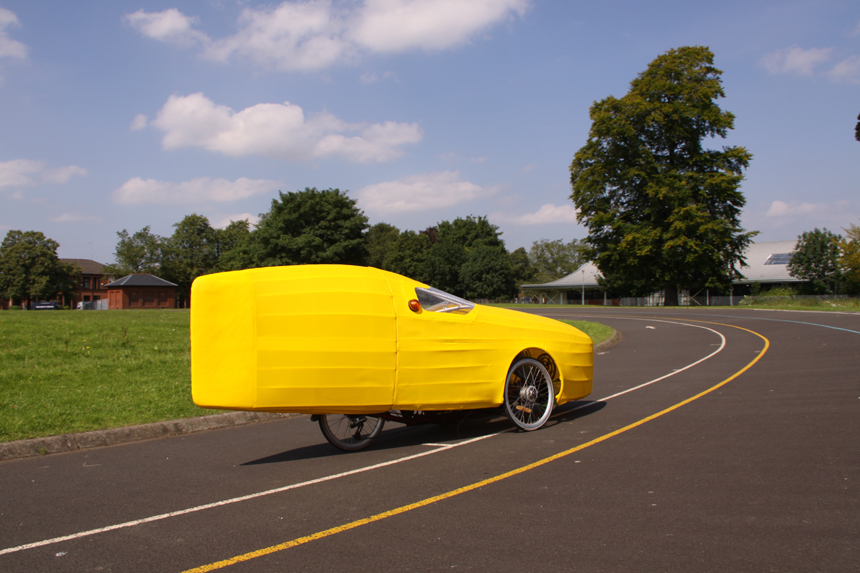
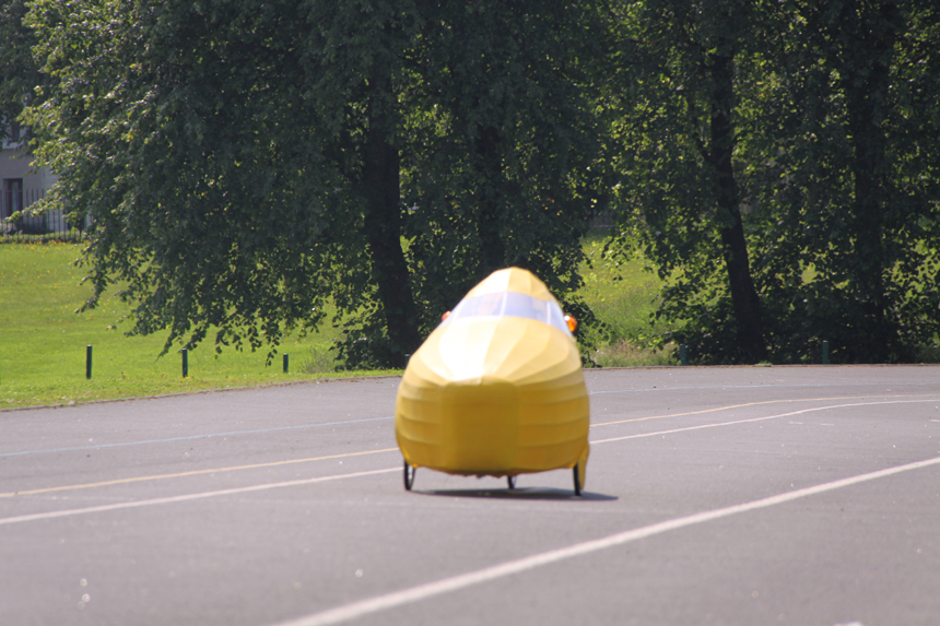
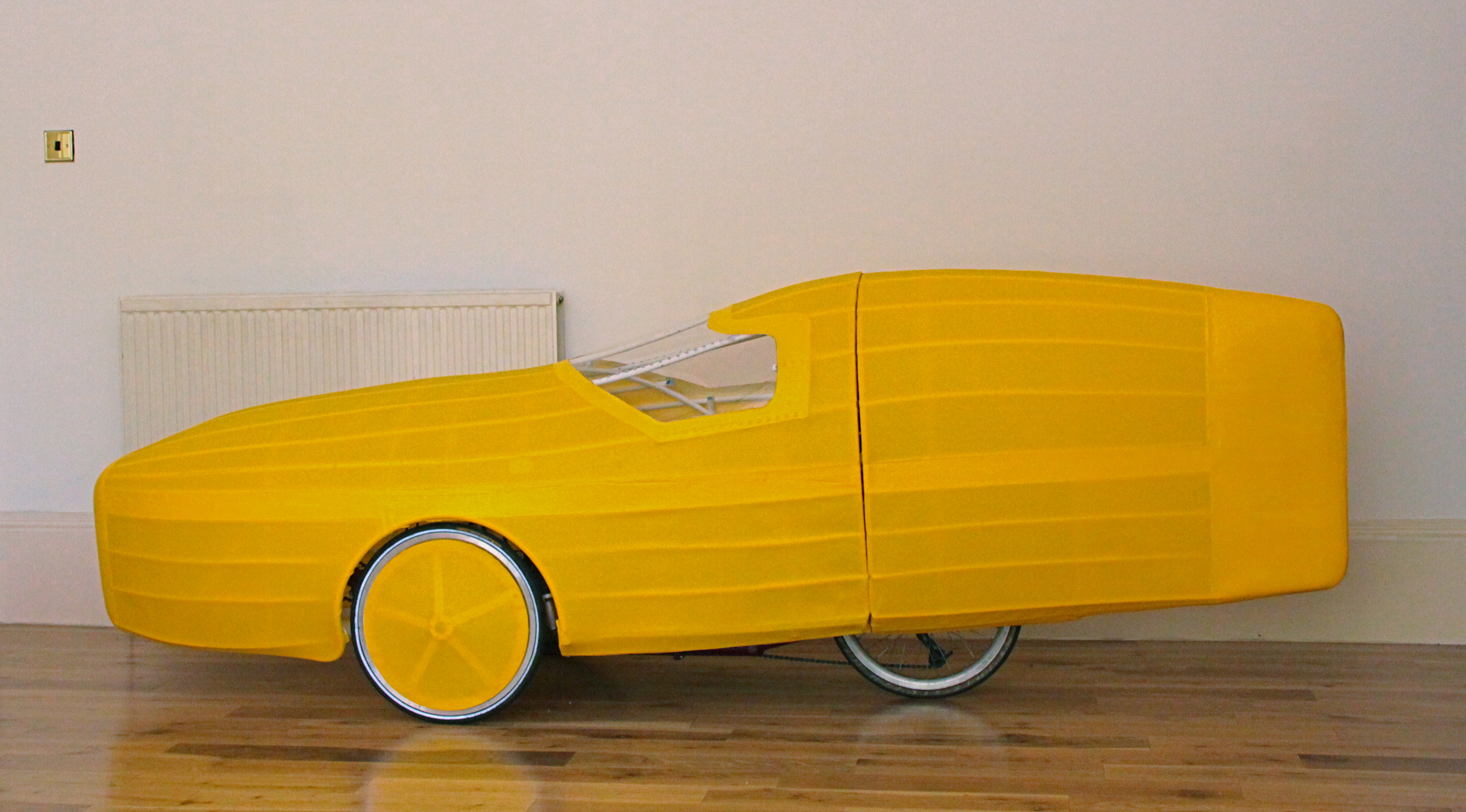
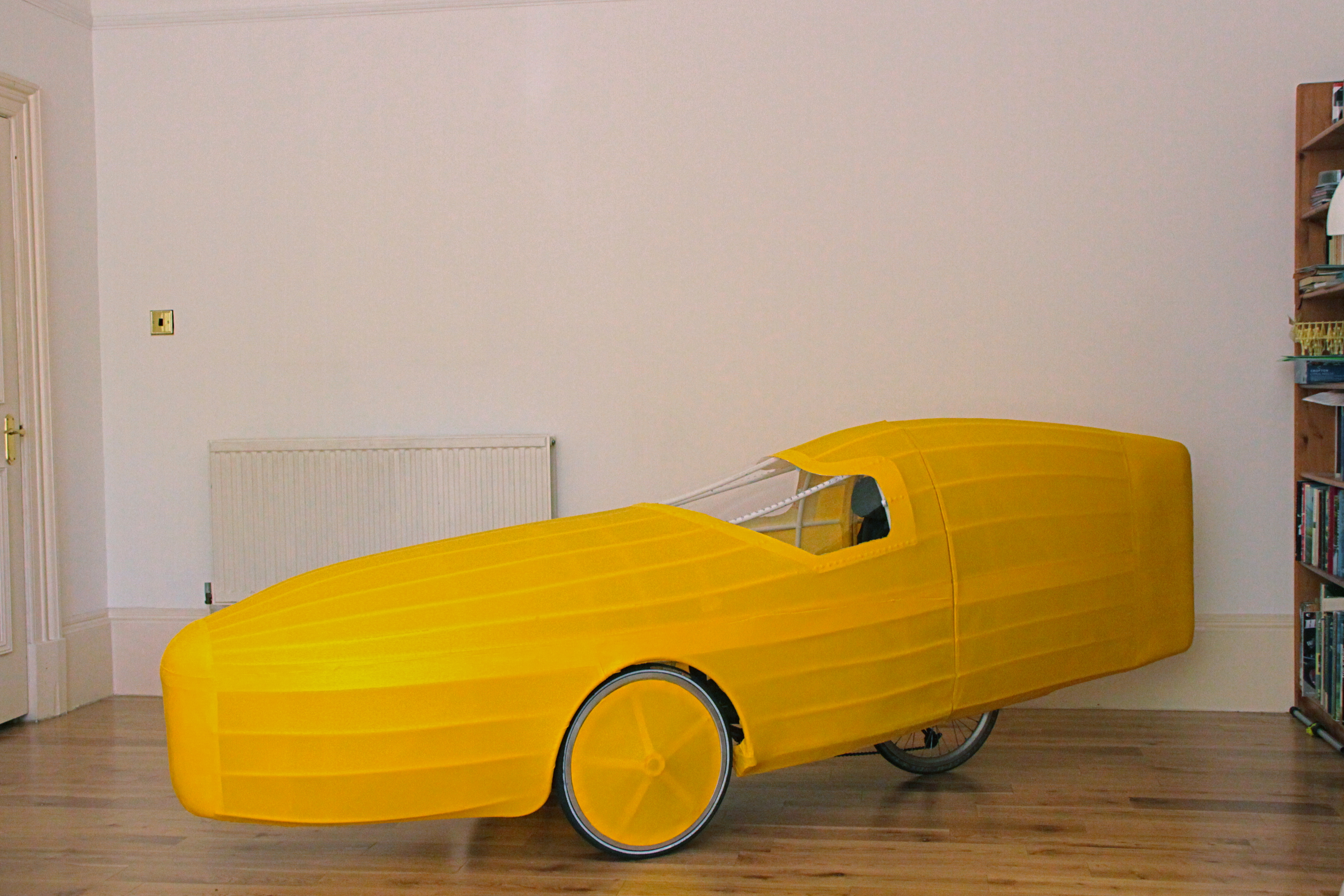
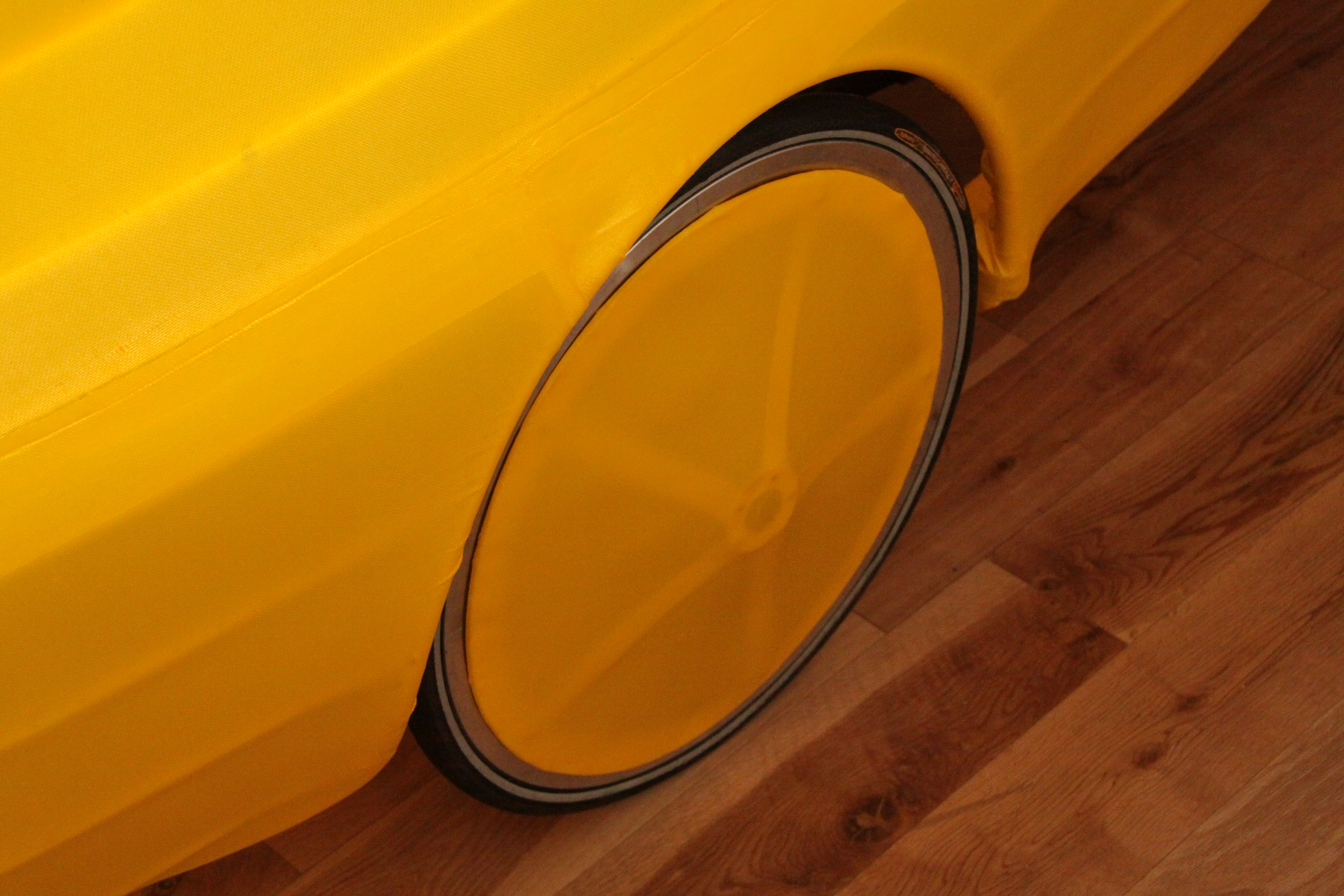
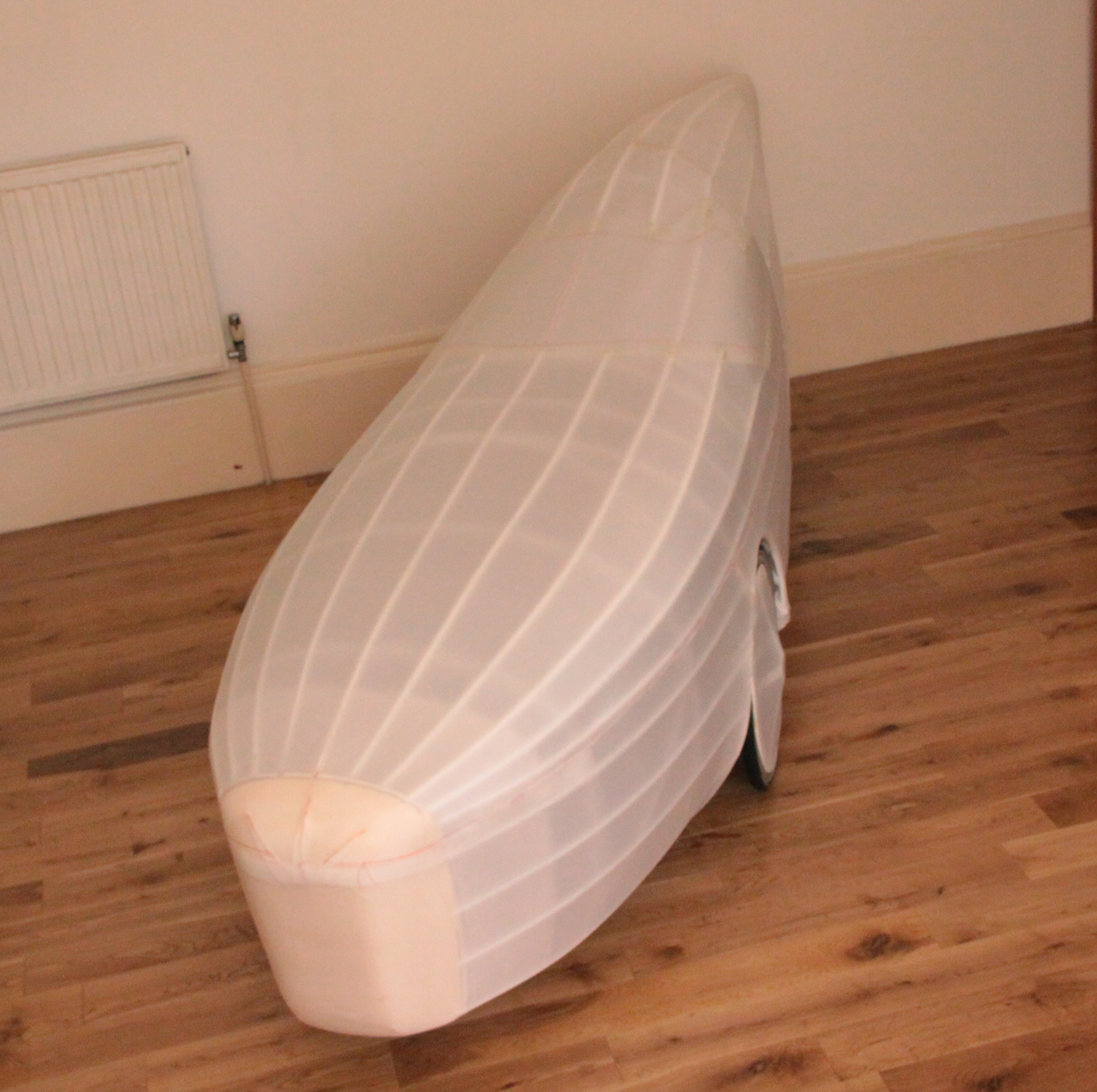
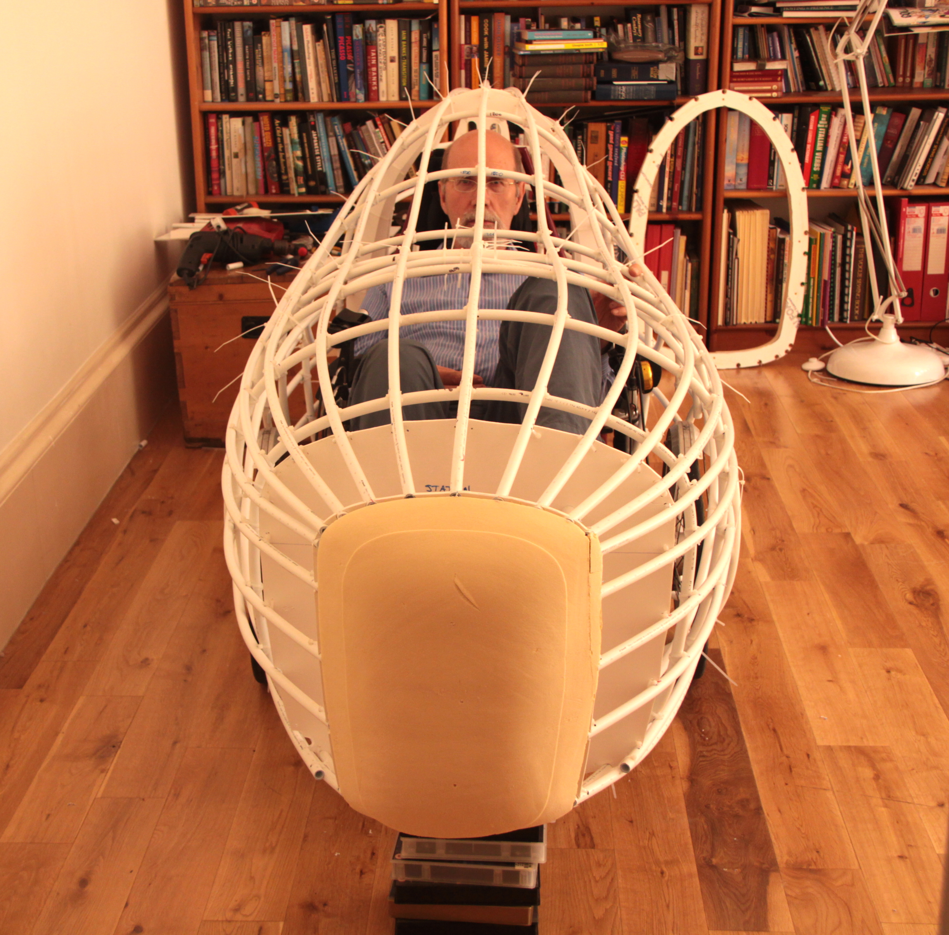
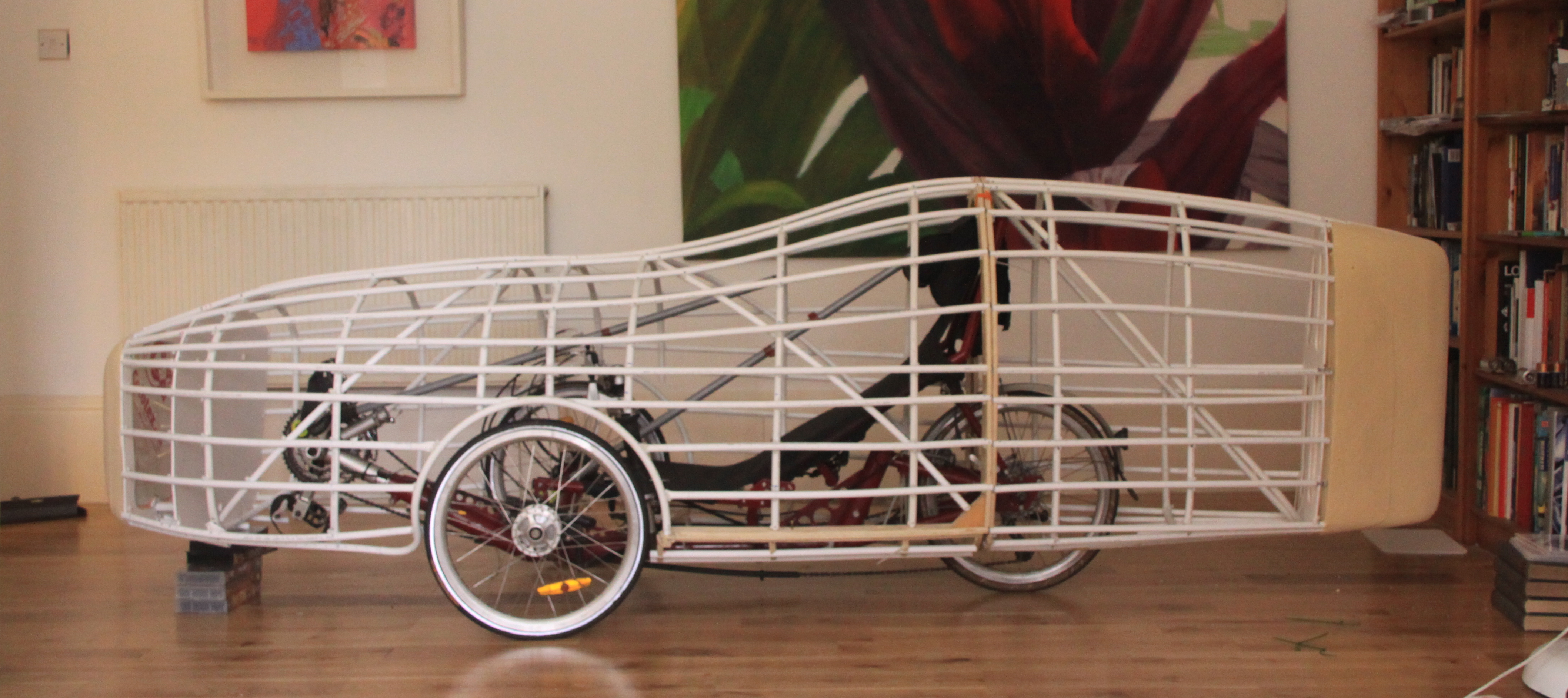
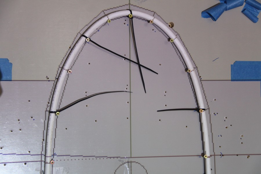
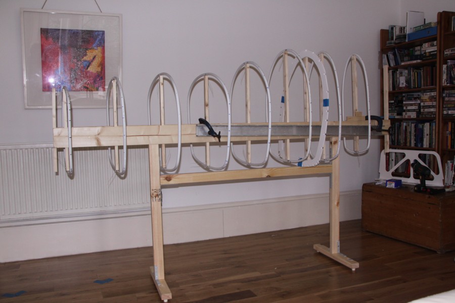
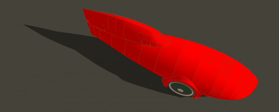
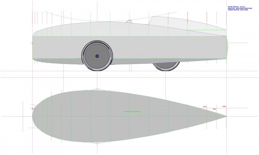
An ideal solution for me would be an enclosed trike or velomobile.

This is what Kenny is busy designing and building.

Regards Charles

Velomobile start of a new project

Charles wants a Velomobile, a small human powered car, to complete a challenge of cycling round Britain. Charles Barnard is a long distance cyclist, he warmed up by doing Lands End to John O’Groats followed by 4,800 kms round the perimeter of France, then capped that by cycling  864 kms along the Pilgrim’s Way, up and over the Pyranees, to Santiago de Compostela, in Galicia, N.W.Spain. All of these expeditions have three things in common, weather, wind and sun. Singly and in combination these elements can be very wearying, to the point of psychological collapse. The answer, Charles decided, is a Velomobile. The shelter will keep you dry and the aerodynamics will reduce the effort required. If the reduction is only 10%,  it is cumulative, day to day, and then over 100 days cycling results in a saving of 10 days in simple terms. That is a lot.


CHARLES TRIKE LAYOUT 1
CHARLES TRIKE LAYOUT 2
CHARLES TRIKE LAYOUT 3
I was introduced to Charles through Walter Galbraith and the Outdoor Group, a walking and cycling club. I told him about my experience building recumbent bikes and aerodynamic Super Mileage cars. and I offered to design and build a body for his recumbent trike. I took initial measurements of his trike for clearance dimensions. The next day I sent Charles a couple of photos of my cars and also one of the construction details.of the Blimp. Nothing really happened for about a couple of months as Charles was, and is, tied up in a property refurbishment in the South. I prepared five 2D sketches laying out options and body plans, open and closed. One of the main topics of discussion had been that I thought Carbon Reinforced Plastic was difficult and messy to prepare, expensive, and worst of all, heavy. I’ll post on this later.
CHARLES TRIKE LAYOUT 4
CHARLES TRIKE LAYOUT 5
All this discussion sbout Velomobiles, got me thinking about building my own for some long distance touring. I resurected a drive system I designed many years ago but never got round to building. It is a Linear Drive which reduces the frontal area of the feet when pedaling. The design for this trike and Charles’ trike body are all based on the principles of using ellipses to generate volumes from one calculted profile to another. I worked up an illustration version to show the difference between that and a plain profile plot. The upper and lower body profiles are NACA 0008. The equator is NACA 16-021. The head faring is also NACA 16-021. All of the plotting co-ordinates are manipulated in an Excel spreadsheet.
CYCLECAR TRIKE LINEAR DRIVE 16021

CYCLECAR TRIKE LINEAR DRIVE 16021 ILLUSThe outcome of our next meeting was although Charles appreciated the 5 examples what he really wanted was my illustration version. I explained he had been seduced by a prettier picture and it is really unwise to set off on a trek round Britain in a untried trike. So I incorporated some of the shape ideas into one of the 5 and set to work building a 3D drawing in Sketchup, which I had only just started using.