
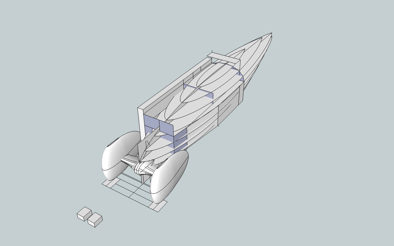
In various drawings you will see blocks and cubes dotted around. These are for handling, they allow you to manipulate the component accurately, Sketchup rotation tools have a hard time handling curved surfaces.
Now I have a quick-and-dirty knock up drawing. some parts are accurately placed but nothing is fixed or final.
The only restriction I have placed on this design is that the maximum width is 800 mm, to go through a door in my apartment.
The first thing I checked for was the sight line, it was way too long.
So I redesigned the body with a straight line nose profile from just below the eyes and clearing the front axle.
It was so ungainly I am not allowing it out in public. Maybe the theory is sound but it does not always produce pleasing results as I found.
Maybe there is work to be done improving visibility without scaring people.
So I went back to body 1.
I had a 20 inch BMX wheel lying around while i was drawing. The smaller diameter rims have a hard time with the condition of the road and cycle track around here. I drew 26 inch 559 wheels and spats.
The increase in surface wetted area and cross sectional area is offset by the decrease in rolling resistance and tyre availability.


The down side of the larger wheels means the air flow between the spats and nose is becoming more restricted and looks like it will generate higher air pressure and therefore drag.
I act on niggles. I am not very smart and it takes time for things to sink in. Then they start to niggle at me, then I have to do something about it. The problem was always there, it is just exaggerated with larger spats.
The thing I tried was to increase the size of the axle fairing and placed so the air travels up the profile increasing in pressure. However when it goes over the hump on both fairing and spats the pressure will be negative by the time it hits the nose which has effectively pushed back.

Body 3.1 is the same but with an enclosed head fairing and a larger rear wheel spat, but this will cause grounding problems.

Body 3.2 Is another variation on the head fairing.

Body 4 gH2Ost Rerun: is the beginning of thinking about the engineering of bending the body to steer the wheels.
I have lying about some 100 mm diameter Tumble Dryer hose, 25 mm compressed length stretches out to 120 mm, while retaining it’s circular form. I also have 80 mm hose.
I needed a semi circular cross section round about the trailing edge of the spats. At the same time I took the opportunity to split the body into two zones.
The upper section for the width of the arms and shoulders and the lower for the rib cage, hips and feet. I used E 817 for the upper profile, angling it in from the spats through clearance at the shoulders to the tail.
I went back to Loft Along Path and this time got it to work. This essentially the same system as ‘gH2Ost’ a tapered central flat section with circular rotated profiles on the edge. The air flow underneath needs more work. The air flow on top is improved and the overall shape is simplified.


With my new found success with LAP I went back to body 1 and rendered all the E 214 profiles.


Body 5. With the body 1 chunk I reversed the trike setup and put the spats at the back. This has the chance of excellent airflow well down the form. I can also reduce the overall width down to +/-600 mm.

