Images for this article can be found in First Prinipals Gallery
While I was delving into the surface of the gigantic field of aerodynamics I came across some figures relating to fish. Birds and humans do a very good job of propelling objects through air, but fish outstrip anything humans can do through water. Hydrodynamics is basically the same problem as aerodynamics, it is just the medium is so much denser and cannot, in any real sense, be compressed. Nuclear submarines with all their gigantic reserves of power can acheive +/-50 knots submerged, or that is what the owners admit to. Sharks have been measured at 55 knots and Blue Marlin have been measured at over 60 knots, admitedly over short distances. Both of these animals have been developing their forms over tens of millions of years. So what is it about their shape that allows them to do this? The first thing that struck me was most fish are not circular in cross section, but elliptical. Now this was not an easy fact to find as in all the web searching I did, I found masses of material, images, giving the distinguishing features of each species but they are all in profile, side-on. Nothing on their cross section. I knew fish are elliptical but I couldn’t prove it. How strange is that?
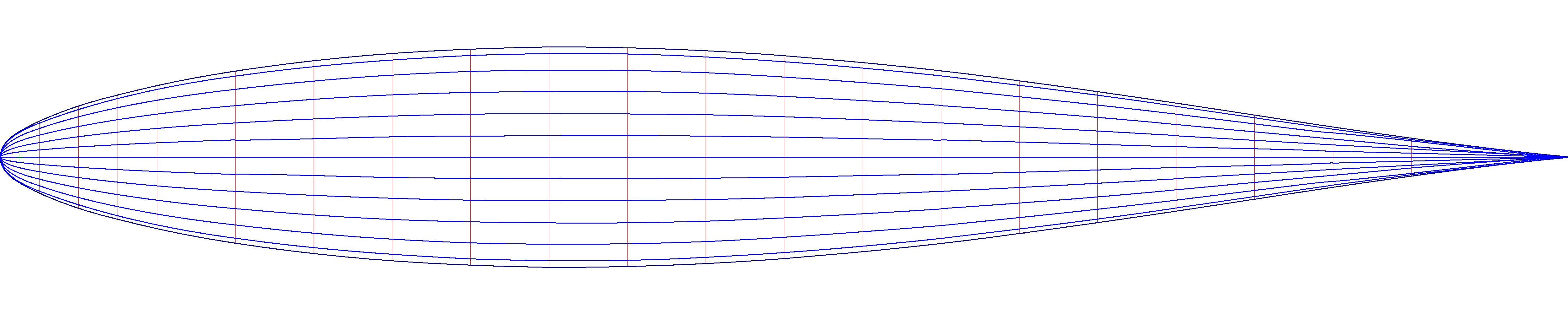
So…..using my trusty 2D drawing package I started to try and generate a fish shape. I took a NACA 63 profile and at each station I drew an ellipse at 0.75, that is the radius is three quarters the radius of the circle at 90 degrees. (Stations are at right angles to length ways axis of a boat or a plane and become the cross section). I then added radii to mark out where the length-way pieces would go, they are know as longerons. In exactly the same way I did with the tool drawings I projected the intersections back to the vertical and horizontal.
I created an elliptical form in three ways;-
By drawing an ellipse using a constant ratio.
By manipulating the co-ordinates in Excel directly at 0.75 and plotting the result.
By applying the formula for an ellipse to the co-ordinate data
The drawing process was by far the simplest and quickest method and for this theoretical phase was accurate enough.
Why bother with all this, why not just draw a line? I had learnt the quickest way to develop something new, and understand it, is by small incremental steps altering only one aspect at a time. If you attempt two or more aspect changes at once it appears to be faster, until something goes wrong. The time required to unravel what has happened and rectify it is much, much longer than if you stick to the pedantic, plodding course. I also did not have anyone to ask, maybe they were there, but I could not describe what I was attempting to do, clearly enough, to ask the question.
So I now had a fish shape, complete with lines, where I could see the form if I married two drawings in my head. I realised that what I was seeing was a shift in shape. If you take a profile and rotate in a circular fashion around the central axis the shape remains constant, the shape at 90 degrees is the same as the shape at 0 degrees. Now if the same shape is rotated around an ellipse the initial profile is the same as the circular path one (90 degrees) but as it moves along the ellipse it is part one and part the final shape at 0 degrees. At half way it is half of one profile and half of the profile at 0 degrees. As it continues around the complete ellipse it returns back to the initial profile.
The next step was to reverse the process and increase the ellipse to 1.25 of the original. This worked just the same, surprise, surprise. Add fins, tail. eyes, bingo, a symmetrical fish. Very few things in the natural world are symmetrical.
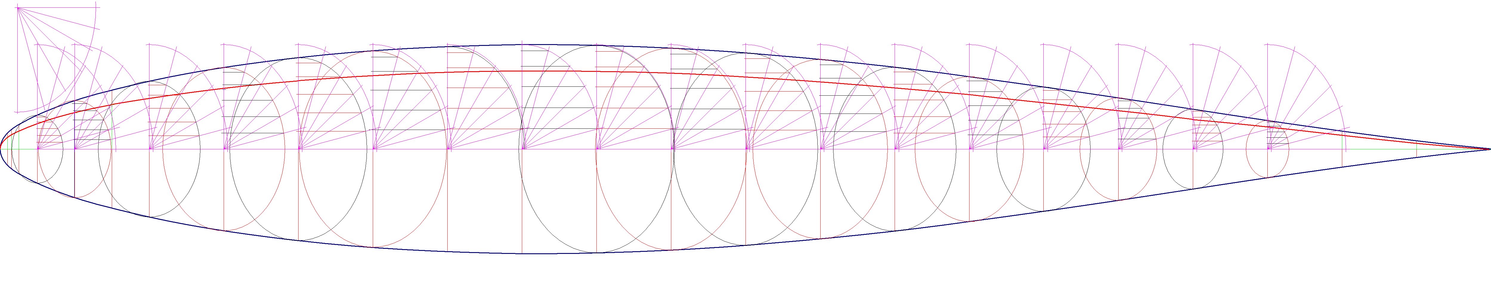
Now this is where it starts to get complex and it is why I was taking such baby steps and I was feeling my way along. I then took two different profiles that had co-ordinate stations which coincided and drew an ellipse between a profile at 0 degrees and another at 90 degrees.
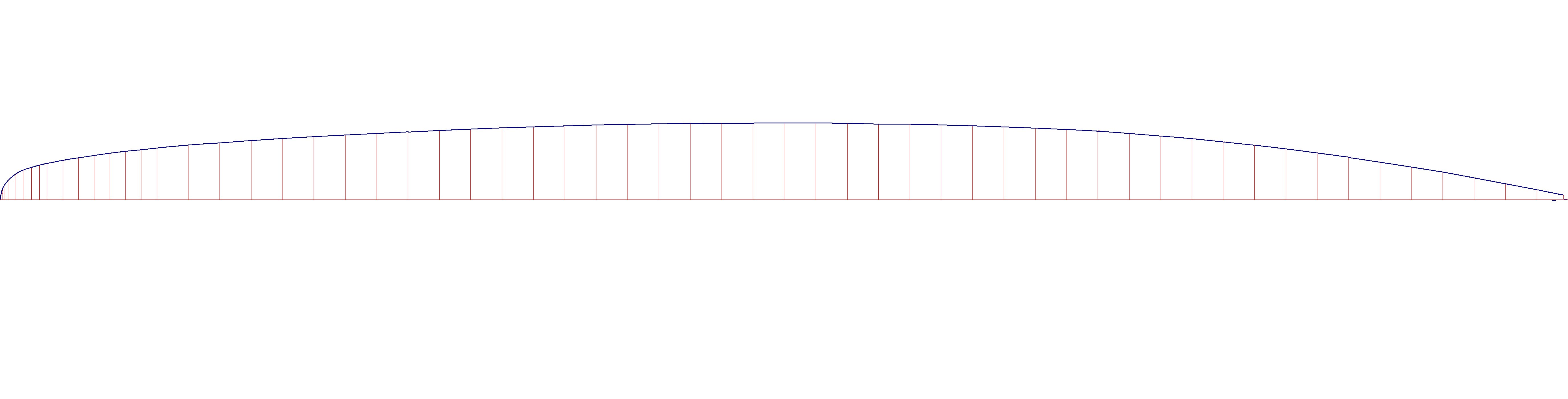
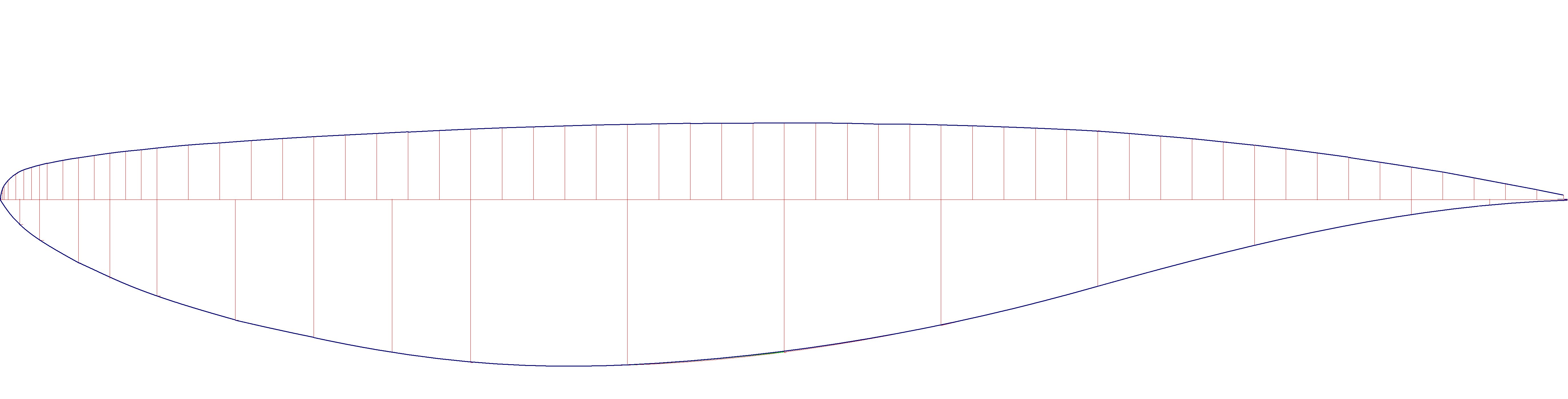
The ratio of the ellipse changes for each station. Using this I connected three different profiles. The upper profile has it’s maximum depth near the back. The central one, the Equator, is more evenly loaded, and the lower profile is front loaded. Each of these profiles in their own right are calculated for minimum drag. The leap of faith I am making is that the shapes generated between these profiles are also minimum drag, although this is by no means a certainty. The resultant shape generated using this method looks remarkably like a Blue Whale. All of the co-ordinate points to make this form are numerical so the shape can be made using CAM (Computer Aided Manufacturing), this is very important.


The final step in this series was to make a shape using four profiles connected by ellipses. If all the profiles are different then the resulting form is assymetrical and looks like your lower leg with the shin bone and three different outlines of the calf muscle. All of this work was done with an ancient version of a simple 2D drawing programme, no 3D work, no Computer Flow Diagnostics, just simple thought process and first principle thinking. I had come to the point where I could ‘see’ what I had generated but I needed to be able to show it to other people in 3D to make it clear.


Who knew ellipses could be so beautiful?!! Looking forward to your next post. 🙂
Stunning! I am really intrigued by your ideas. Look forward to the next entry. Great work Ken.