
What follows is from the first of nine iterations is the development of a system to generate thrust from the wind, using first principle thinking.
Humankind discovered if you held a surface up, in the wind, it exerted a pull. In the case of kites, it is string or rope, with a boat it is called a mast, which is a big upright stick. Another stick was used to stretch the surface out. Different conditions across the world required different arrangements. Fishing, transport, cargo, warfare, discovery and competition all have their own different developments. All have the common drawback of the mast creating bad airflow around itself and an obstruction to easy sail handling. The weight of the mast and rigging and forces from the wind were and are usually led to the boat’s strongest member, the keel.

This is an initial sketch of ideas collected together to see what they look like. I choose one idea and give it more thought and work. I then stop, assess and analyse, and if a drawback out-ways the advantage then it is set aside, but not rejected. Later ideas and developments can redress the balance and make something feasible. The biggest difficulty, I find, is keeping sight of what I am trying to achieve, but not knowing how to get there, because no one has gone there before, that I know of. A simile would be, searching for a black cat in pitch-black room without knowing the size of the room nor what a cat is.

I wanted to hold a sail up into the wind but remove the stick. So I chose a catenary arch, one great advantage being it gets stronger the more it is loaded. Brunelleschi used it the structure of his cathedral in Florence and Gaudi in the Sagrada Familia in Barcelona. The best way to introduce loads into a tube is tangentially. The sail is held up centrally and rotates inside the arch. However this leads to the area being too small, so I added a second mast and sail.

3D printing enables very accurate manufacturing of aerofoil shapes, both straight and curved. The essential feature of a catenary arch is if the loads are kept within the limits of the structure it remains incredibly strong. Here is an illustration of the cross section with a width (chord) of 100 mm with a Teflon tube 8 mm with a 6 mm Internal Diameter (ID). 5 mm Dyneema rope with a breaking strain of 2500 kg runs through this and transmits tension through the sail back into the bottom of the mast, equally to both sides.

This is a screenshot of the slicing programme output of a vertically extruded printed core with internal bracing. Presently there are machines that can print to 2.1 metres high, although I have encountered vibration problems with smaller scale objects.

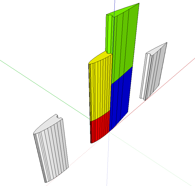
This represents exactly the same cross section but extruded horizontally and split vertically, enabling curved items to be printed.
These curved sections are then bonded together in a ‘’brickwork’’ fashion so no joins run across the complete width of the structure.
