A hatch is very important to be able to adjust and work on the sails. They have to seal against the force of the sea and wind driven spray.
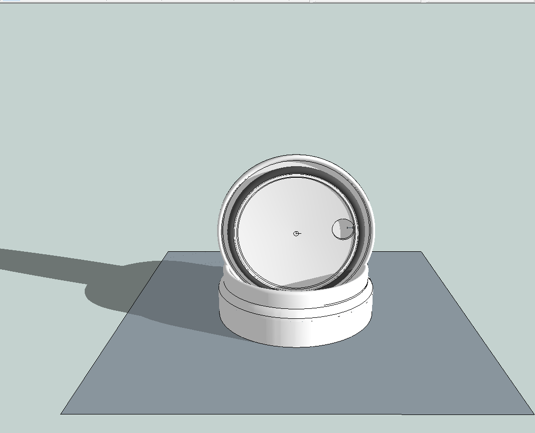
This illustration shows a circular hatchway in a notional deck plane. Above is the cover with a pneumatic seal, which can be inflated to 50 psi. or 3.45 bar. The seal is a bicycle tyre, large, strong, smooth without tread and a folding bead made from flexible Kevlar. The inflation valve will protrude above and below deck
The cover is sealed into the hatchway.
The cover cannot go through the hatchway because the diameter is greater. Then where to store the cover?, have it hinged?, or attach it with a rope and have it banging about in the wind and waves ? Not good.
Making the hatch system oval makes no difference to the tyre if it is the same effective circumference. I took the opportunity to add a window made from polycarbonate (Lexan ???) for interior light and being able to watch the sails and wind direction. It a double glazed system to reduce interior condensation.
The cover can now go through the hatch way and be stored below, safely. There will be handles attached to make the operation easier. Also a tether to stop it blowing away in a gust.
This second iteration of the sail has a symmetrical shape around central tensioning. The boom controls the sail, acts as an end plate to stop any thrust bleeding away. It also collects the skin and battens when reefed and completes the structure of the mast.. The whole assembly swivels on the central point. Again the mast has no significant effect on sail apart from holding it up.
Battens help to give shape to the sail material which has been cut and joined to give an aero-foil shape. The design of this batten comes directly from studying the nine section tail of a dragonfly. It is to be integrated inside the sail in pockets. The semi circular shapes are interlocking hinges, held together under compression. Between each section there are angled shoulders when all are closed on one side to form an E347 profile. On reflection I thought this made the sail too clumsy to build and may well suffer from too much wear to the pockets. Start again.
Here is a schematic of a batten on the boom to give me an idea of size of structure. This is a great break-through drawing because I saw the central tension should be applied not at the centre of the area (1/2 chord) of the sail but as close to the point of aero thrust generation. As the sail moves from one side (tack) to the other the central section barely moves. At this point I envisioned radiused tracks to maintain tension on the leading and tailing edges of the sail, (Leach and Luff) I had not got very far resolving the fixtures.
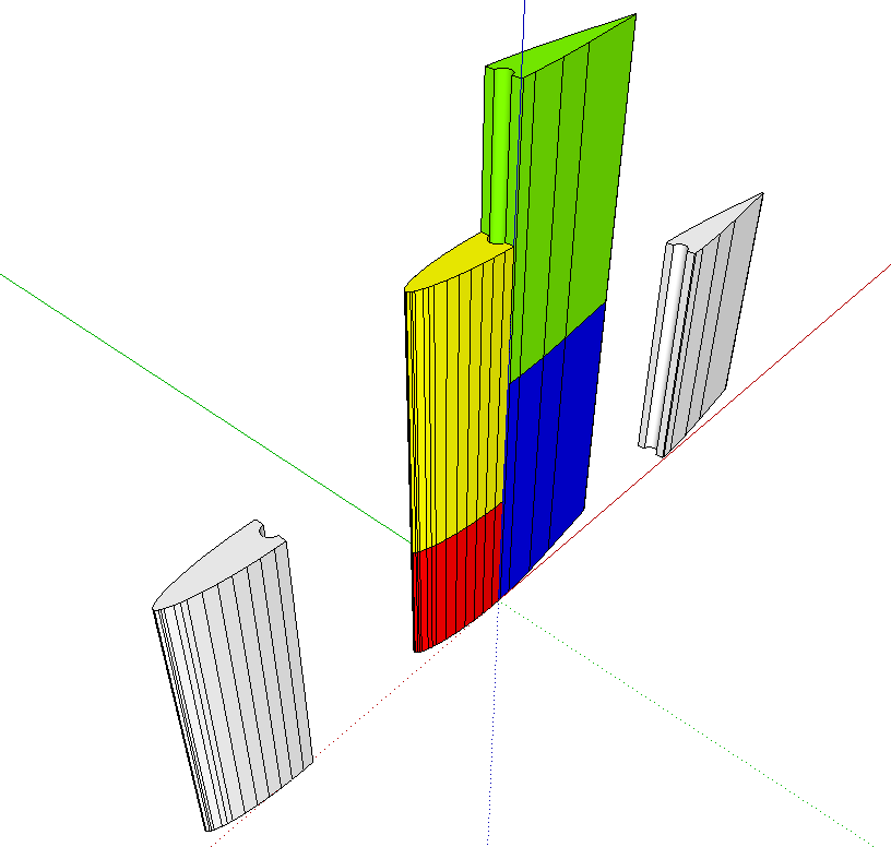
The breakthrough resulted in this wide, low aspect ratio, rig with a fore /aft mast. The boom is now a jointed trellis structure. Fairings can be added to reduce windage drag. The major advantage to this being the effort from the thrust of the sail can be accurately placed for the best characteristics of the hull shape. The red, central panel represents car seat belt webbing with a breaking point of 2500 kg. Handily it comes compatible with seat belt latches which are made from high grade stainless steal.
The big drawback is it’s ugly, clumsy, difficult to work around and ugly. Start again.
The batten was simplified from nine sections to seven. This image shows on the underside the shoulders have closed and the gaps on the top side show the angles that create a simplified E347 in the tensioned webbing. The whole sail surface is moulded together with the battens.
I decided to reduce the sail area, reduce the forces, make the battens all the same length and extend the tension system to the leading and trailing edges. The sail area is relatively low compared to racing boats, but by having two sets they can be balanced around the Centre of Lateral Resistance (CLR)
The boom is jointed and takes up the shape of the sail. The sail material is bonded to the webbing and batten sections.
To reef the sail the tension is released from below, through the mast, and sail lowered. The central latch is released and the one from above attached then either end are done, one at a time. At no time is the sail released from the boom and is always held by two connections. The tension is re-applied.
Tension is maintained in the moulding of the sail, especially to give the offset nature of the top webbings. The first is to the leading edge, the second to the centre, the third to the sail at the same angle (45 deg.) as the first, and the fourth to the trailing edge. Reducing tension very slightly from below, through the boom, on the centre web will increase the arc in the battens.
What follows is from the first of nine iterations is the development of a system to generate thrust from the wind, using first principle thinking.
Humankind discovered if you held a surface up, in the wind, it exerted a pull. In the case of kites, it is string or rope, with a boat it is called a mast, which is a big upright stick. Another stick was used to stretch the surface out. Different conditions across the world required different arrangements. Fishing, transport, cargo, warfare, discovery and competition all have their own different developments. All have the common drawback of the mast creating bad airflow around itself and an obstruction to easy sail handling. The weight of the mast and rigging and forces from the wind were and are usually led to the boat’s strongest member, the keel.
This is an initial sketch of ideas collected together to see what they look like. I choose one idea and give it more thought and work. I then stop, assess and analyse, and if a drawback out-ways the advantage then it is set aside, but not rejected. Later ideas and developments can redress the balance and make something feasible. The biggest difficulty, I find, is keeping sight of what I am trying to achieve, but not knowing how to get there, because no one has gone there before, that I know of. A simile would be, searching for a black cat in pitch-black room without knowing the size of the room nor what a cat is.
I wanted to hold a sail up into the wind but remove the stick. So I chose a catenary arch, one great advantage being it gets stronger the more it is loaded. Brunelleschi used it the structure of his cathedral in Florence and Gaudi in the Sagrada Familia in Barcelona. The best way to introduce loads into a tube is tangentially. The sail is held up centrally and rotates inside the arch. However this leads to the area being too small, so I added a second mast and sail.
3D printing enables very accurate manufacturing of aerofoil shapes, both straight and curved. The essential feature of a catenary arch is if the loads are kept within the limits of the structure it remains incredibly strong. Here is an illustration of the cross section with a width (chord) of 100 mm with a Teflon tube 8 mm with a 6 mm Internal Diameter (ID). 5 mm Dyneema rope with a breaking strain of 2500 kg runs through this and transmits tension through the sail back into the bottom of the mast, equally to both sides.
This is a screenshot of the slicing programme output of a vertically extruded printed core with internal bracing. Presently there are machines that can print to 2.1 metres high, although I have encountered vibration problems with smaller scale objects.
This represents exactly the same cross section but extruded horizontally and split vertically, enabling curved items to be printed.
These curved sections are then bonded together in a ‘’brickwork’’ fashion so no joins run across the complete width of the structure.
One incident in particular literally shaped this boat. Sven was interviewed in Madeira. He had to turn back from a single handed attempt to sail to New Zealand, round Cape Horn.
The boat he built was good, made with the best materials, but he realised it was not good enough to risk the worst conditions there are. Sven was very despondent, usually he is very positive. He did not have enough money to ship the boat back to Sweden, nor to scrap it, craneage, transport and disposal cost.
As good starting point, I thought, was to design everything to fit into a standard 20 ft. shipping container, the red box represents the internal dimensions.
The drawings are 3D CAD turned into illustrations, life size and show the core of the structure. No plugs, moulds, wastage and minimum sanding. All surfaces to be covered in high strength organic composites. The very minimum use of hydro-carbon based materials is the major target.
There are printers, at present, big enough to produce this design, so this is not sci-fi, nor photoshop fantasy.
This is not a racing boat.
As with the 1 metre pond yacht, the aero profile is Eppler 347. It is used for the hull sails, masts, keels and modified for the superstructure.
There are two small sails, so one person can manage the power and handle the reduction of area (reefing).
Aerodynamics are as important as hydrodynamics, so there are no drag inducing handrails, standing or running rigging nor lines. All controls for sail management and steering are internal.
The yellow ovals are hatches and are pneumatically sealed.
Here is the boat leaning at 38.7 degrees, there is no change to the under-water shape, so there will be no change in handling characteristics.
It is designed to exist in the water like a fish, not fight the element, but carefully divert the water with minimum disturbance. It should go through the waves not climb over them. Sealed against leakage rather than trying to cope with the after effects of deluge and soaking clothing and bedding.
Dried out on a sandy beach, waiting on the tide. The figure is included to give scale to what is really quite a small boat. There is enough clearance under the hull to land on a beach of small rocks.
The keels act as a jig, in construction, to align the 1 metre sections for bonding
The tail is the full extent of the Eppler 347 to complete the flow around the hull with as little disturbance as possible.
This is the starting point of an idea that developed into a much larger project.
Aerodynamics and hydrodynamics are very similar, apart from water is about 1000 times more dense than air. I had a couple of ideas concerning the reduction of drag in a sailing boat. In order to test them I could build a pond yacht, to 1 metre class rules, and run side by side comparisons. In that way I could avoid all the work, expense and endless, endless sanding of building a full size boat.
Until recently boat designers have taken huge amounts of resources optimising surface areas in contact with water. Aerodynamics have been largely ignored in the mistaken belief that they do not come into play until much higher speeds are in play. In this design anything that could induce drag was discarded, simplifying the design.
The hull is Eppler 347 profile, as are the wing, fin and bulb, and is 1 metre long. The cross section is circular.
I chose an Eppler aero profile #347 for it’s low drag characteristics while also retaining enough ‘’body’’ to make a viable hull. This was rotated 360 degrees and left complete. There is no rudder system shown, possibly the keel foil can be used to steer.
As the screenshots show the hull can lean up to 80 degrees from upright with no change in hydrodynamic shape, characteristics or handling, being able to sail full on at 80 degrees lean. The bow is intended to move the water aside without creating a large bow wave and also go through a wave. Traditional bows finely cut the water but also ride up over a wave creating a rhythmic rocking-horse motion.
Yacht at 0 degrees.Yacht at 45 degrees.Yacht at 80 degrees. The under-water, hydrodynamic, shape remains exactly the same as 0 degrees.
The sail/wing/mast is a symmetrical E347 divided into leading edge mid-section and tail-section and hinged. The controls run up through the midsection and apply torque at the base and half way up, to orient the sections into a power generating aero foil. There are no standing rigging or lines, therefore no drag.
The nose and tail section are rotated at 7 1/2 degreesThis is a later iteration showing the hinge section, with spacing for printed thin wall skins. The main central support is reinforced carbon fibre tubing
The gaps between each section can be sealed with Teflon strip, edge-on. This may stop, or reduce, pressure equalising from low to high.
The lower parallel section and upper, tapered, section of the wing.
The major flaw to this wing system is being unable to reduce the effective sail area without becoming overly complicated and heavy.
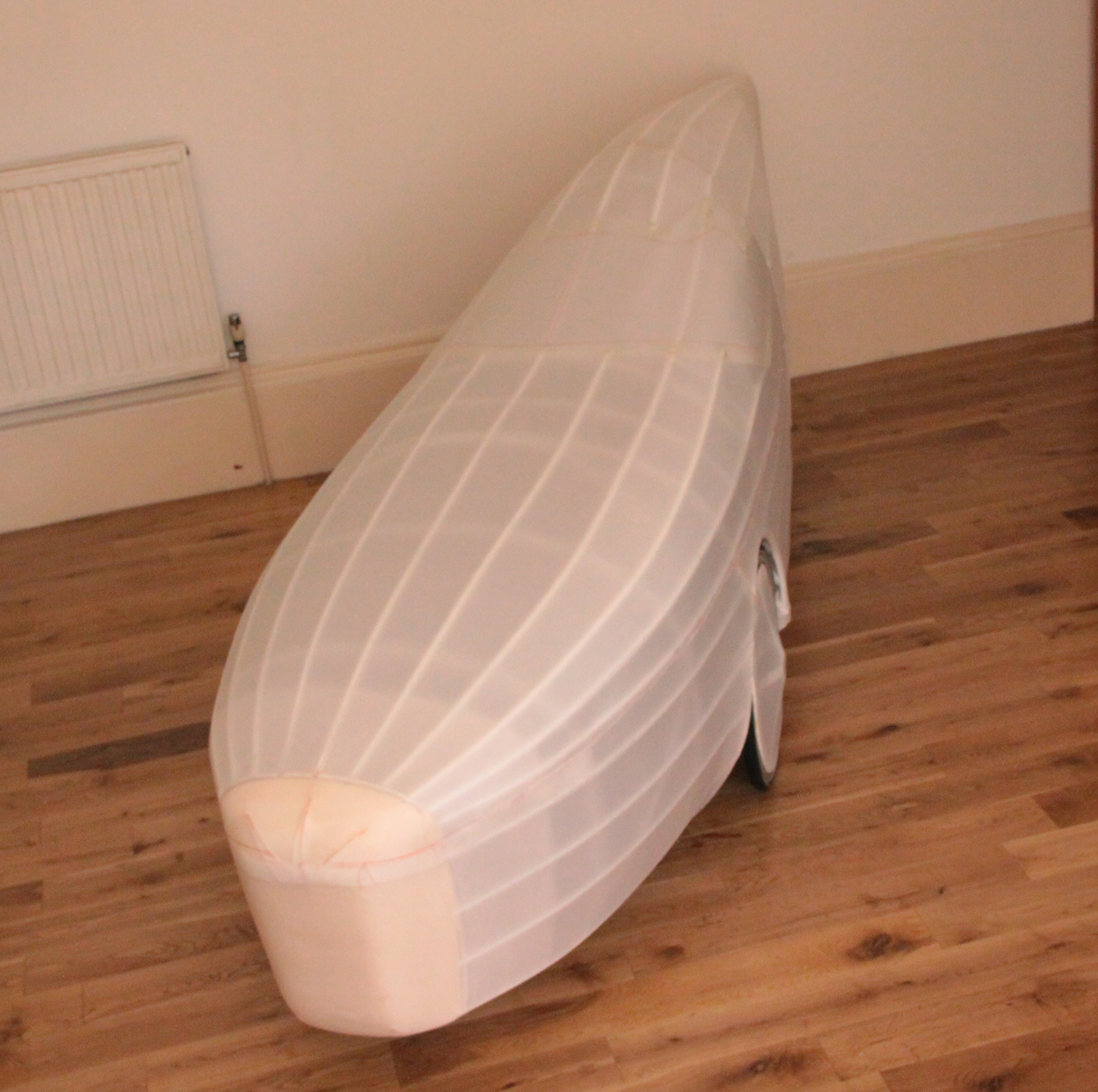
The skin was cut using the pre- shrunk pattern. I had to learn how to use a sewing machine to do this, so it is NOT perfect. It now has to be sealed and painted with acrylic mediums and paint. I use Golden acrylics.
Side elevation
The wheel covers are PVC Foam rims and hubs with Corex spokes covered withe Dacron.
Three quarters above
The tail is covered by sewing the two halves along the spine,
Nose and wheel well
The Dacron is heavy duty polyester sourced from Kudzo Craft. It is used for covering kayaks and small boats. I did not think aircraft fabric would hold up to being handled 200+ times on a long ride.
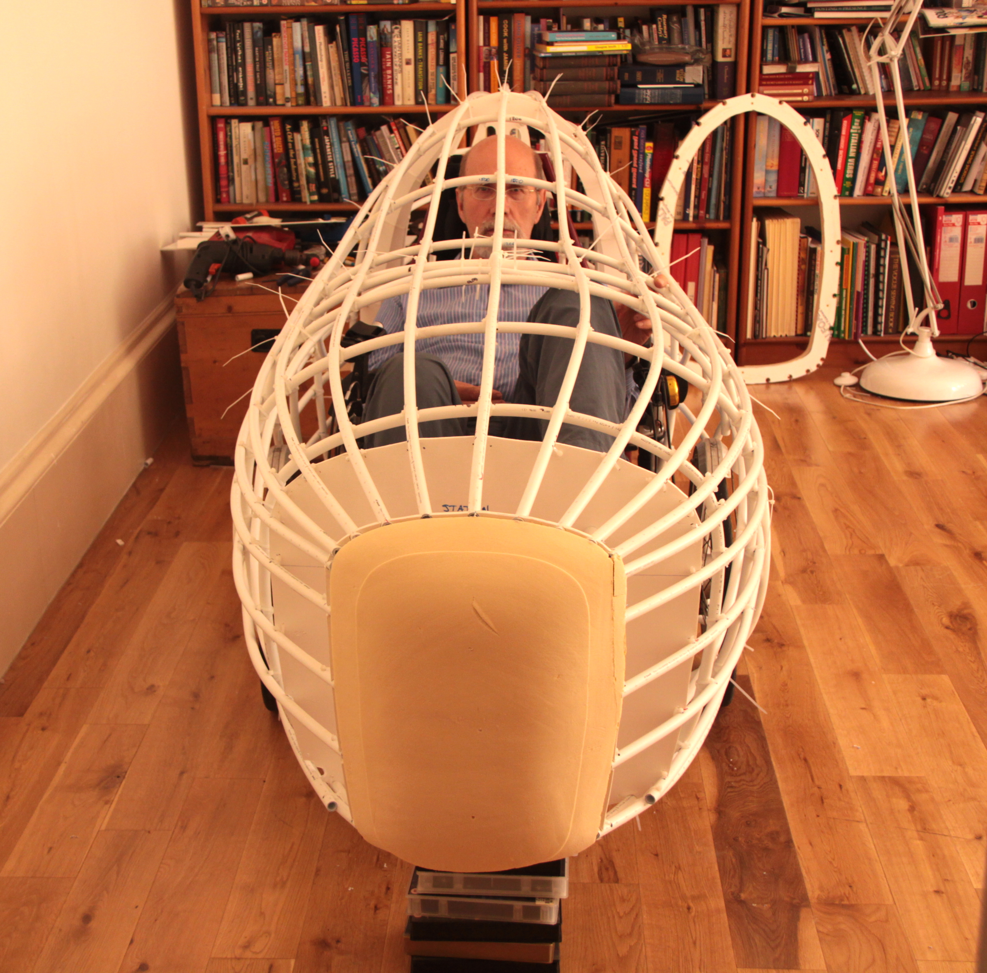
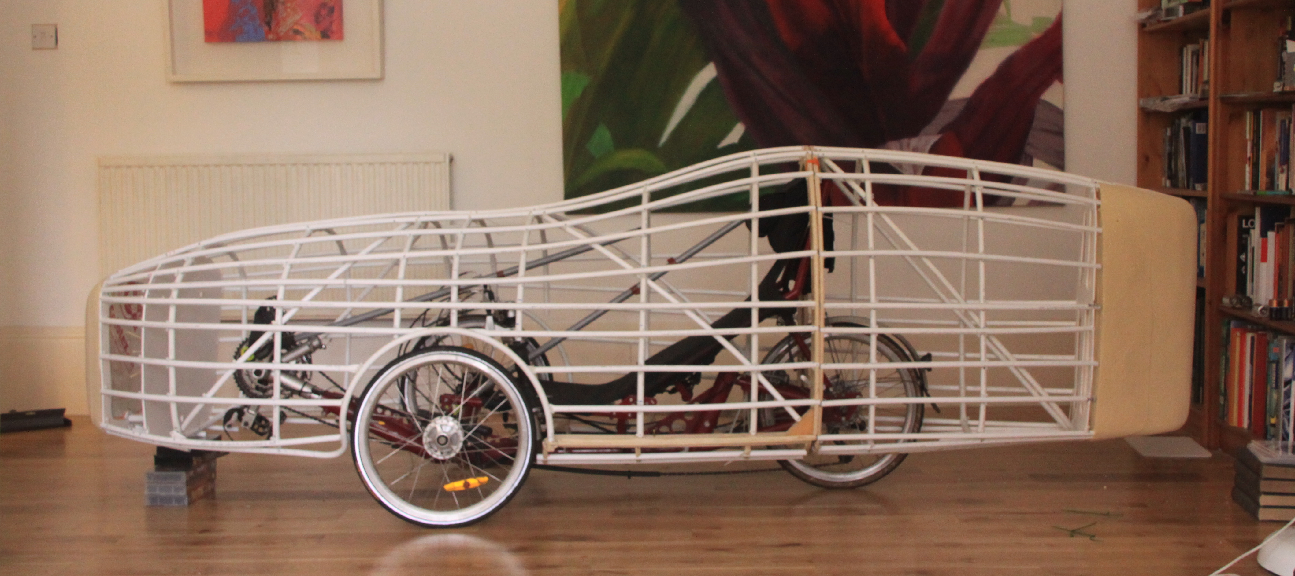
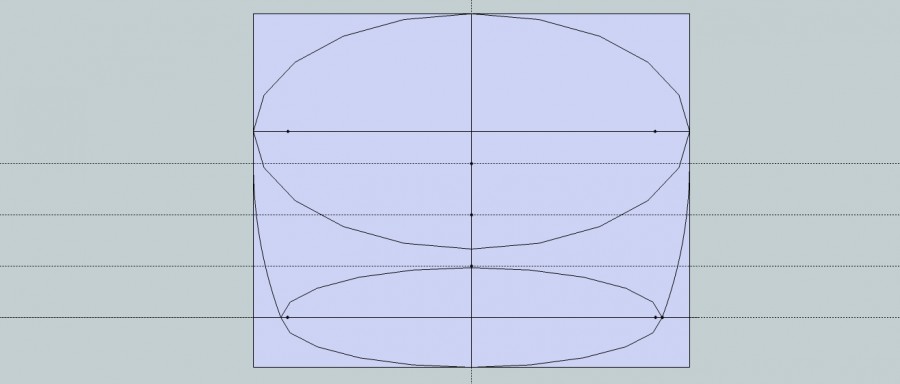
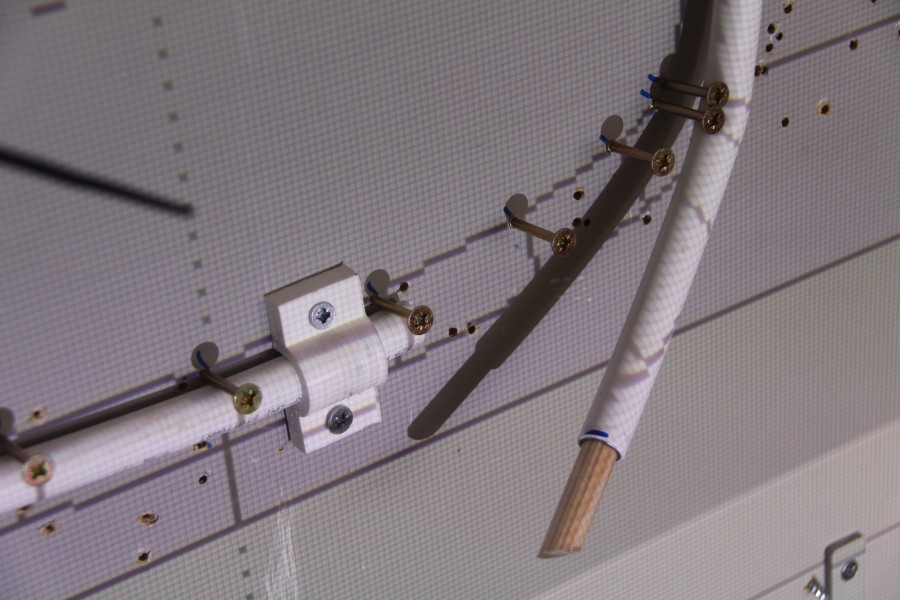
Once we had agreed the drawing Layout One.1 was a good starting point for a build, I started the process of converting the outline drawings to working ones. This means placing the 28 lengthways 15 mm pipe (longerons) inside the outer skin. I started with the 900 mm Station and made it the Master. This has a registration box that is used in each seperate Station, and remains identical throughout. My initial idea was to print the Station on to paper and use that as a template to cut flat boards. The registration box stops the programme deciding what size each one is best for you.
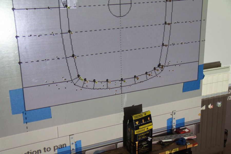
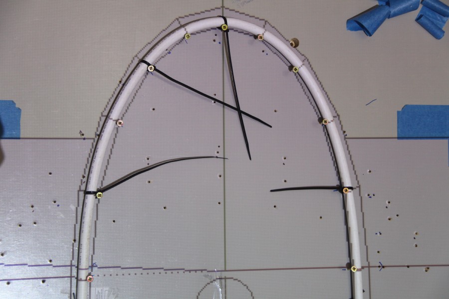
Two things happened about the same time, I bought a laptop projector and Davy Jamieson introduced me to underfloor heating pipe. At 16 mm it has 2 layers like the PVC plumbing pipe, but it has an added layer of aluminium. When you bend it it retains the shape. I redid the drawings with 15 mm and 16 mm pipe and projected the drawing directly on to a board, taped in the registration box on the board and the feet of the Workmate and tripod on the floor
.
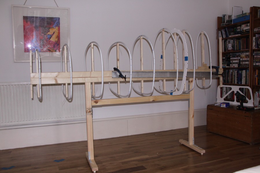
I built a frame called a Strong Back to support and keep all the Stations properly spaced and in line. I should have stayed with my first plan of using aluminium extrusions. It is more expensive but it would not have twisted and warped like the timber in the centrally heated atmos. However this failure has lead to a solution which could give great benefits to structural frame strength and building simplicity, more later.
Charles and I then lashed the structure together loosely with zip-ties. At this stage nothing is really finalised, the drawing is one thing, what we have here is another and it can be useful go with what evolves rather than rigidly pursue an ideal.
At this time, a couple of years ago. I became aware of 3D printing. After a fair amount of surfing and reading I discovered http://reprap.org/wiki/RepRapA project started at Bath University under the leadership of Adrian Bowyer. It is Open Source and has had a huge influence in spreading the technology of 3D printing. RepRap stands for printers which can (self) REPlicate RAPidly. This is exactly what I was looking for. I could draw it in 3D, print it, develop the thinking and forms, redraw and reprint.
The process starts with a drawing made in Sketchup http://www.sketchup.com a free-ware programme which started life as an architectural CAD package and has developed into product design and sketching. The simple drawing is then transferred to Slic3r where the object is “sliced” into 0.25 mm layers, this data is then transferred to Pronterface where it is converted into G-code to instruct the machine on how to move and with the correct amount of plastic. Sketchup is a great programme because it appears simple, very straight forward and accurate. I regularly work in 3 decimal places of a millimeter, that is sufficient for what I want to do at the moment.
I bought a Prusa Mendel machine kit and built the mechanical hardware. I needed help with the electrics and a friend Walter Galbraith, a lecturer in Electronic Engineering, came and sorted out the wiring. I don’t speak electricity at all. It started as a hobby, building and learning about this new machine and getting it running. I was working on another project and realised I needed a clamp to hold some tubing in place. I measured up the pipe, drew it up in Sketchup, put it through Slic3r, Proterface and started to print in 17 minutes. The end result is EXACTLY what I need, not close or just about, but exactly what is needed. At this point the printer changes from an interesting past-time to an essential tool.