Velomobile design: Iterations

LAYOUT 1.3.2RED OH

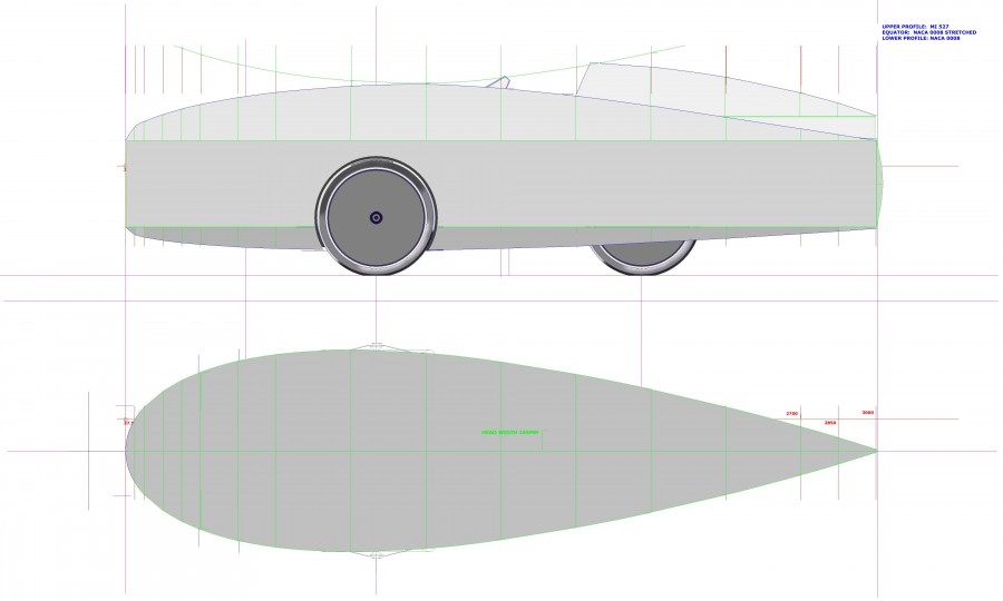
I made a start on a Sketchup 3D drawing to have something to point sticks and throw rocks at. The first task is to cover the rider and front wheels. I wanted to keep a simple shape, and deal seperately with the head above the shoulders to give minimum frontal area. The body frontal area is determined by the height and width of the shoulders, and the height of the knees as they cycle. The wheels cause a lot of turbulence. If you enclose them, then the body has to be wide enough for steering clearance at full lock. If you try to pursue one aspect of a design for purity of function it has a terrible habit of showing up flaws in another area. I don’t like compromise, but trying to find the best balance of the least offensive solutions is often the most you can hope for. I had already been through this with the “Blimp”, so that seemed a good starting point for development.

LAYOUT THREE COMBINE 1

Building the drawing in two parts and combining them was too much lke hard work and showed up how difficult the real construction could be. So I combined the head faring into the main body, at the cost of increased frontal area.

LAYOUT THREE COMBINE 1.5 nose

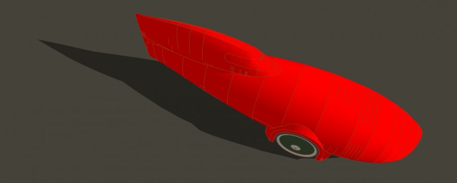
This looked OK until I put in the clearnce for the feet. This gave two ‘nostrils’ which appeared to be scooping air into the body.

LAYOUT THREE COMBINE 1.5

I added an air-dam but this unbalanced the look badly, I tried an elliptical dam guiding the air around the wheels and away again, but again it looked very difficult to build and keep light. The dam would have be able to to rise over Speed Bumps, adding complication, weight and jamming.

LAYOUT ONE.1

In order to divert the air around the feet I lowered nose, and the tail, to smooth the air flow and balance the shape.

LAYOUT ONE.1.1

LAYOUT ONE.1.3

Velomobile start of a new project

Charles wants a Velomobile, a small human powered car, to complete a challenge of cycling round Britain. Charles Barnard is a long distance cyclist, he warmed up by doing Lands End to John O’Groats followed by 4,800 kms round the perimeter of France, then capped that by cycling  864 kms along the Pilgrim’s Way, up and over the Pyranees, to Santiago de Compostela, in Galicia, N.W.Spain. All of these expeditions have three things in common, weather, wind and sun. Singly and in combination these elements can be very wearying, to the point of psychological collapse. The answer, Charles decided, is a Velomobile. The shelter will keep you dry and the aerodynamics will reduce the effort required. If the reduction is only 10%,  it is cumulative, day to day, and then over 100 days cycling results in a saving of 10 days in simple terms. That is a lot.


CHARLES TRIKE LAYOUT 1
CHARLES TRIKE LAYOUT 2
CHARLES TRIKE LAYOUT 3
I was introduced to Charles through Walter Galbraith and the Outdoor Group, a walking and cycling club. I told him about my experience building recumbent bikes and aerodynamic Super Mileage cars. and I offered to design and build a body for his recumbent trike. I took initial measurements of his trike for clearance dimensions. The next day I sent Charles a couple of photos of my cars and also one of the construction details.of the Blimp. Nothing really happened for about a couple of months as Charles was, and is, tied up in a property refurbishment in the South. I prepared five 2D sketches laying out options and body plans, open and closed. One of the main topics of discussion had been that I thought Carbon Reinforced Plastic was difficult and messy to prepare, expensive, and worst of all, heavy. I’ll post on this later.
CHARLES TRIKE LAYOUT 4
CHARLES TRIKE LAYOUT 5
All this discussion sbout Velomobiles, got me thinking about building my own for some long distance touring. I resurected a drive system I designed many years ago but never got round to building. It is a Linear Drive which reduces the frontal area of the feet when pedaling. The design for this trike and Charles’ trike body are all based on the principles of using ellipses to generate volumes from one calculted profile to another. I worked up an illustration version to show the difference between that and a plain profile plot. The upper and lower body profiles are NACA 0008. The equator is NACA 16-021. The head faring is also NACA 16-021. All of the plotting co-ordinates are manipulated in an Excel spreadsheet.
CYCLECAR TRIKE LINEAR DRIVE 16021

CYCLECAR TRIKE LINEAR DRIVE 16021 ILLUSThe outcome of our next meeting was although Charles appreciated the 5 examples what he really wanted was my illustration version. I explained he had been seduced by a prettier picture and it is really unwise to set off on a trek round Britain in a untried trike. So I incorporated some of the shape ideas into one of the 5 and set to work building a 3D drawing in Sketchup, which I had only just started using.


RepRap 3D printing

Trying to describe what I wanted to do proved to be very difficult. I realised I needed a 3D drawing package, I asked a few people where to start to look. The range stretches from Free-ware to professional packages costing many thousands of pounds. The general consensus was to go for Blender, it is a package used for modeling 3D animated figures and rendering illustrations. The modeling principle is essentially creating a form in 3D space and then distorting it until you arrive at a result you can live with. I found it’s a very good programme, but not the way I wanted to work. I tried a couple of 3D CAD samples but they were massively competent but quite clumsy to handle, just too much.RepRap Prusa Mendel

At this time, a couple of years ago. I became aware of 3D printing. After a fair amount of surfing and reading I discovered http://reprap.org/wiki/RepRap A project started at Bath University under the leadership of Adrian Bowyer. It is Open Source and has had a huge influence in spreading the technology of 3D printing. RepRap stands for printers which can (self) REPlicate RAPidly. This is exactly what I was looking for. I could draw it in 3D, print it, develop the thinking and forms, redraw and reprint.

The process starts with a drawing made in Sketchup http://www.sketchup.com a free-ware programme which started life as an architectural CAD package and has developed into product design and sketching. The simple drawing is then transferred to Slic3r where the object is “sliced” into 0.25 mm layers, this data is then transferred to Pronterface where it is converted into G-code to instruct the machine on how to move and with the correct amount of plastic. Sketchup is a great programme because it appears simple, very straight forward and accurate. I regularly work in 3 decimal places of a millimeter, that is sufficient for what I want to do at the moment.

IMG_2608

I bought a Prusa Mendel machine kit and built the mechanical hardware. I needed help with the electrics and a friend Walter Galbraith, a lecturer in Electronic Engineering, came and sorted out the wiring. I don’t speak electricity at all. It started as a hobby, building and learning about this new machine and getting it running. I was working on another project and realised I needed a clamp to hold some tubing in place. I measured up the pipe, drew it up in Sketchup, put it through Slic3r, Proterface and started to print in 17 minutes. The end result is EXACTLY what I need, not close or just about, but exactly what is needed. At this point the printer changes from an interesting past-time to an essential tool.

IMG_2576_2